1 THERMAL SCIENCES
The analysis of renewable energy systems requires a solid understanding of energy conversion processes, transformation between various forms of energy, and ways of defining efficiencies of energy producing and consuming systems. In this chapter, we review fundamental concepts of thermodynamics, heat transfer, fluid mechanics, thermochemistry, power plants, and refrigeration systems to form a solid and useful foundation for the renewable energy systems to be covered in the upcoming chapters.
The physical sciences that deal with energy and the transfer, transport, and conversion of energy are usually referred to as thermal-fluid sciences or just thermal sciences. Traditionally, the thermal-fluid sciences are studied under the subcategories of thermodynamics, heat transfer, and fluid mechanics (Çengel and Ghajar, 2015; Çengel et al., 2016; Çengel and Cimbala, 2018; Çengel et al., 2019).
The design and analysis of most thermal systems such as power plants, automotive engines, refrigerators, building heating and cooling systems, boilers, heat exchangers, and other energy conversion equipment involve all categories of thermal sciences. For example, designing a solar collector involves the determination of the amount of energy transfer from a knowledge of thermodynamics, the determination of the size of the heat exchanger using heat transfer, and the determination of the size and type of the pump using fluid mechanics (Fig. 2-1).
2 THERMODYNAMICS
Thermodynamics can be defined as the science of energy. Although everybody has a feeling of what energy is, it is difficult to give a precise definition for it. Energy can be viewed as the ability to cause changes. The name thermodynamics stems from the Greek words therme (heat) and dynamis (power), which is most descriptive of the early efforts to convert heat into power. Today the same name is broadly interpreted to include all aspects of energy and energy transformations including power generation, refrigeration, and relationships among the properties of matter.
One of the most fundamental laws of nature is the conservation of energy principle. It simply states that during an interaction, energy can change from one form to another but the total amount of energy remains constant. That is, energy cannot be created or destroyed. A rock falling off a cliff, for example, picks up speed as a result of its potential energy being converted to kinetic energy. The conservation of energy principle also forms the backbone of the diet industry: A person who has a greater energy input (food) than energy output
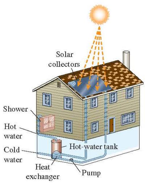
Figure 2-1 The design and analysis of renewable energy systems, such as this solar hot water system, involves thermal sciences.
(exercise) will gain weight (store energy in the form of fat), and a person who has a smaller energy input than output will lose weight. The change in the energy content of a body or any other system is equal to the difference between the energy input and the energy output, and the energy balance is expressed as (E{\text {in }}-E{\text {out }}=\Delta E_{\text {system }}).
The first law of thermodynamics is simply an expression of the conservation of energy principle, and it asserts that energy is a thermodynamic property. The second law of thermodynamics asserts that energy has quality as well as quantity, and actual processes occur in the direction of decreasing quality of energy. For example, a cup of hot coffee left on a table eventually cools, but a cup of cool coffee in the same room never gets hot by itself. The high-temperature energy of the coffee is degraded (transformed into a less useful form at a lower temperature) once it is transferred to the surrounding air.
Heat and Other Forms of Energy
Energy can exist in numerous forms such as thermal, mechanical, kinetic, potential, electrical, magnetic, chemical, and nuclear, and their sum constitutes the total energy (E) (or (e) on a unit mass basis) of a system. The forms of energy related to the molecular structure of a system and the degree of the molecular activity are referred to as the microscopic energy. The sum of all microscopic forms of energy is called the internal energy of a system, and is denoted by (U) (or (u) on a unit mass basis).
The international unit of energy is joute (J) or kilojoule ( (1 \mathrm{~kJ}=1000 \mathrm{~J}) ). In the English system, the unit of energy is the British thermal unit (Btu),which is defined as the energy needed to raise the temperature of 1 lbm of water at 60 by (1^{\circ} \mathrm{F}). The magnitudes of kJ and Btu are almost identical ( (1 \mathrm{Btu}=1.055056 \mathrm{~kJ})). Another well-known unit of energy is the calorie ( (1 \mathrm{cal}=4.1868 \mathrm{~J}) ), which is defined as the energy needed to raise the temperature of 1 g of water at 14.5 by (1^{\circ} \mathrm{C}).
Internal energy may be viewed as the sum of the kinetic and potential energies of the molecules. The portion of the internal energy of a system associated with the kinetic energy of the molecules is called sensible energy or sensible heat. The average velocity and the degree of activity of the molecules are proportional to the temperature. Thus, at higher temperatures the molecules possess higher kinetic energy, and as a result, the system has a higher internal energy.
The internal energy is also associated with the intermolecular forces between the molecules of a system. These are the forces that bind the molecules to each other, and, as one would expect, they are strongest in solids and weakest in gases. If sufficient energy is added to the molecules of a solid or liquid, they will overcome these molecular forces and simply break away, turning the system to a gas. This is a phase change process and because of this added energy, a system in the gas phase is at a higher internal energy level than it is in the solid or the liquid phase. The internal energy associated with the phase of system is called latent energy or latent heat.
The changes mentioned above can occur without a change in the chemical composition of a system. Most heat transfer problems fall into this category, and one does not need to pay any attention to the forces binding the atoms in a molecule together. The internal energy associated with the atomic bonds in a molecule is called chemical (or bond) energy, whereas the internal energy associated with the bonds within the nucleus of the atom itself is called nuclear energy. The chemical and nuclear energies are absorbed or released during chemical or nuclear reactions, respectively.
In the analysis of systems that involve fluid flow, we frequently encounter the combination of properties (u) and (P v). For the sake of simplicity and convenience, this combination is defined as specific enthalpy (h) or just enthalpy. We perefer the term enthalpy for convenience. That is, (h=u+P v), where the term (P v) represents the flow energy of the fluid (also called the flow work), which is the energy needed to push a fluid and to maintain flow. In the energy analysis of flowing fluids, it is convenient to treat the flow energy as part of the energy of the fluid and to represent the microscopic energy of a fluid stream by enthalpy (h) (Fig. 2-2).
Specific Heats of Gases, Liquids, and Solids
An ideal gas is defined as a gas that obeys the relation
[
P v=R T \quad \text { or } \quad P=\rho R T
]
where (P) is the absolute pressure, (v) is the specific volume, (T) is the thermodynamic (or absolute) temperature, (\rho) is the density, and (R) is the gas constant. It has been experimentally observed that the ideal gas relation given above closely approximates the (P-v-T) behavior of real gases at low densities. At low pressures and high temperatures, the density of a gas decreases and the gas behaves like an ideal gas. In the range of practical interest, many familiar gases such as air, nitrogen, oxygen, hydrogen, helium, argon, neon, and krypton
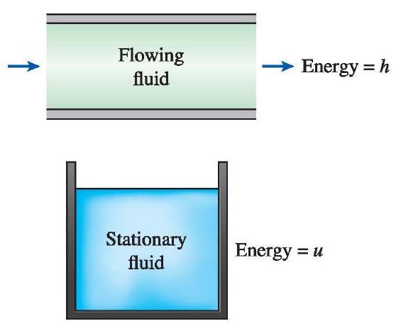
Figure 2-2 The internal energy (u) represents the microscopic energy of a nonflowing fluid, whereas enthalpy (h) represents the microscopic energy of a flowing fluid.
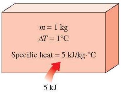
Figure 2-3 Specific heat is the energy required to raise the temperature of a unit mass of a substance by one degree in a specified way.
and even heavier gases such as carbon dioxide can be treated as ideal gases with negligible error (often less than (1 \%) ). Dense gases such as water vapor in steam power plants and refrigerant vapor in refrigerators, however, should not always be treated as ideal gases since they usually exist at a state near saturation.
Specific heat is defined as the energy required to raise the temperature of a unit mass of a substance by one degree (Fig. 2-3). In general, this energy depends on how the process is executed. We are usually interested in two kinds of specific heats: specific heat at constant volume (c{v}) and specific heat at constant pressure (c{p}). The specific heat at constant volume (c{v}) can be viewed as the energy required to raise the temperature of a unit mass of a substance by one degree as the volume is held constant. The energy required to do the same as the pressure is held constant is the specific heat at constant pressure (c{p}). The specific heat at constant pressure (c{p}) is greater than (c{\nu}) because at constant pressure the system is allowed to expand and the energy for this expansion work must also be supplied to the system. For ideal gases, these two specific heats are related to each other by (c{p}=c{v}+R).
A common unit for specific heats is (\mathrm{kJ} / \mathrm{kg} \cdot{ }^{\circ} \mathrm{C}) or (\mathrm{kJ} / \mathrm{kg} \cdot \mathrm{K}). Notice that these two units are identical since (\Delta T\left({ }^{\circ} \mathrm{C}\right)=\Delta T(\mathrm{~K})), and (1^{\circ} \mathrm{C}) change in temperature is equivalent to a change of 1 K . Also,
[
1 \mathrm{~kJ} / \mathrm{kg} \cdot{ }^{\circ} \mathrm{C}=1 \mathrm{~J} / \mathrm{g} \cdot{ }^{\circ} \mathrm{C}=1 \mathrm{~kJ} / \mathrm{kg} \cdot \mathrm{~K}=1 \mathrm{~J} / \mathrm{g} \cdot \mathrm{~K}
]
and
[
1 \mathrm{Btu} / \mathrm{lbm} \cdot{ }^{\circ} \mathrm{F}=1 \mathrm{Btu} / \mathrm{lbm} \cdot \mathrm{R}
]
The specific heat of a substance, in general, depend on two independent properties such as temperature and pressure. For an ideal gas, however, they depend on temperature only (Fig. 2-4). At low pressures all real gases approach ideal gas behavior, and therefore their specific heats depend on temperature only.
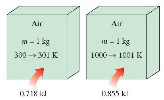
Figure 2-4 The specific heat of a substance changes with temperature.
The differential changes in the internal energy (u) and enthalpy (h) of an ideal gas can be expressed in terms of the specific heats as
[
d u=c{v} d T \quad \text { and } \quad d h=c{p} d T
]
The finite changes in the internal energy and enthalpy of an ideal gas during a process can be expressed approximately by using specific heat values at the average temperature as
[
\Delta u=c{\text {yavg }} \Delta T \quad \text { and } \quad \Delta h=c{p \text { pavg }} \Delta T \quad(\mathrm{~kJ} / \mathrm{kg})
]
or
[
\Delta U=m c{\text {v,avg }} \Delta T \quad \text { and } \quad \Delta H=m c{p, \text { avg }} \Delta T \quad(\mathrm{~kJ})
]
where (m) is the mass of the system.
A substance whose specific volume (or density) does not change with temperature or pressure is called an incompressible substance. The specific volumes of solids and liquids essentially remain constant during a process, and thus they can be approximated as incompressible substances without sacrificing much in accuracy.
The constant-volume and constant-pressure specific heats are identical for incompressible substances (Fig. 2-5). Therefore, for solids and liquids the subscripts on (c{v}) and (c{p}) can be dropped and both specific heats can be represented by a single symbol, (c). That is, (c{p}=) (c{v}=c). This result could also be deduced from the physical definitions of constant-volume and constant-pressure specific heats. Specific heats of several common gases, liquids, and solids are given in the appendix.
The specific heats of incompressible substances depend on temperature only. Therefore, the change in the internal energy of solids and liquids can be expressed as
[
\Delta U=m c{\text {avg }} \Delta T \quad(\mathrm{~kJ})
]
where (c{\text {avg }}) is the average specific heat evaluated at the average temperature. Note that the internal energy change of the systems that remain in a single phase (liquid, solid, or gas) during the process can be determined very easily using average specific heats.
Energy Transfer
Energy can be transferred to or from a given mass by two mechanisms: heat transfer (Q) and work W. An energy interaction is heat transfer if its driving force is a temperature difference. Otherwise, it is work. A rising piston, a rotating shaft, and an electrical wire crossing the system boundaries are all associated with work interactions. Work done per unit time is called power and is denoted by (\dot{W}). The unit of power is kW or (\mathrm{hp}(1 \mathrm{hp}=0.746 \mathrm{~kW})).
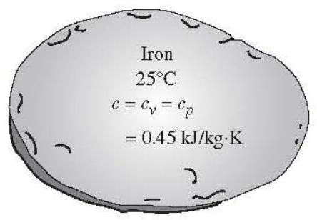
Figure 2-5 The (c{v}) and (c{p}) values of incompressible substances are identical and are denoted by (c).
Car engines and hydraulic, steam, and gas turbines produce work; compressors, pumps, and mixers consume work. Notice that the energy of a system decreases as it does work, and increases as work is done on it.
The amount of heat transferred during the process is denoted by (Q). The amount of heat transferred per unit time is called heat transfer rate and is denoted by (\dot{Q}). The overdot stands for the time derivative, or "per unit time." The heat transfer rate (\dot{Q}) has the unit (\mathrm{kJ} / \mathrm{s}) (or Btu/h), which is equivalent to kW . In cooling applications, the rate of cooling provided by the cooling equipment (cooling capacity) is often expressed in "ton of refrigeration" units where 1 ton (=12,000 \mathrm{Btu} / \mathrm{h}).
When the rate of heat transfer (\dot{Q}) is available, then the total amount of heat transfer (Q) during a time interval (\Delta t) can be determined from
[
Q=\int_{0}^{\Delta t} \dot{Q} d t
]
provided that the variation of (\dot{Q}) with time is known. For the special case of (\dot{Q}=) constant, the equation above reduces to
[
\mathrm{Q}=\dot{\mathrm{Q}} \Delta t \quad(\mathrm{~kJ})
]
The First Law of Thermodynamics
The first law of thermodynamics, also known as the conservation of energy principle, states that energy can neither be created nor be destroyed during a process; it can only change forms. Therefore, every bit of energy must be accounted for during a process. The conservation of energy principle (or the energy balance) for any system undergoing any process may be expressed as follows: The net change (increase or decrease) in the total energy of the system during a process is equal to the difference between the total energy entering and the total energy leaving the system during that process.
Noting that energy can be transferred to or from a system by heat, work, and mass flow, and that the total energy of a simple compressible system consists of internal, kinetic, and potential energies, the energy balance for any system undergoing any process can be expressed as
[
E{\text {in }}-E{\text {out }}=\Delta E_{\text {system }}
]
In the absence of significant electric, magnetic, motion, gravity, and surface tension effects (i.e., for stationary simple compressible systems), the change in the total energy of a system during a process is simply the change in its internal energy. That is, (\Delta E{\text {system }}=\Delta U{\text {sptem }}).
Energy balance can be written in the rate form, as
[
\dot{E}{\text {in }}-\dot{E}{\text {out }}=d E_{\text {ssstem }} / d t \quad(\mathrm{~kW})
]
Energy is a property, and the value of a property does not change unless the state of the system changes. Therefore, the energy change of a system is zero if the state of the system does not change during the process, that is, the process is steady. The energy balance in this case reduces to (Fig. 2-6)
[
\dot{E}{\text {in }}=\dot{E}{\text {out }} \quad(\mathrm{kW})
]
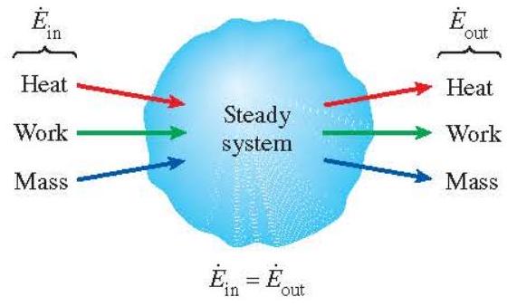
Figure 2-6 In steady operation, the rate of energy transfer to a system is equal to the rate of energy transfer from the system.
Energy Balance for Closed Systems
A closed system consists of a fixed mass. The total energy (E) for most systems encountered in practice consists of the internal energy (U). This is especially the case for stationary systems since they do not involve any changes in their velocity or elevation during a process. The energy balance relation in that case reduces to
Stationary closed system:
[
E{\text {in }}-E{\text {out }}=\Delta U=m c{v} \Delta T
]
where we expressed the internal energy change in terms of mass (m), the specific heat at constant volume (c{v}), and the temperature change (\Delta T) of the system. When the system involves heat transfer only and no work interactions across its boundary, the energy balance relation further reduces to (Fig. 2-7)
Stationary closed system, no work:
[
\mathrm{Q}=m c_{v} \Delta T \quad(\mathrm{~kJ})
]
where (Q) is the net amount of heat transfer to or from the system. This is the form of the energy balance relation we will use most often when dealing with a fixed mass.
Energy Balance for Steady-Flow Systems
A large number of engineering devices such as water heaters and car radiators involve mass flow in and out of a system, and are modeled as control volumes. Most control volumes are analyzed under steady operating conditions. The term steady means no change with time at
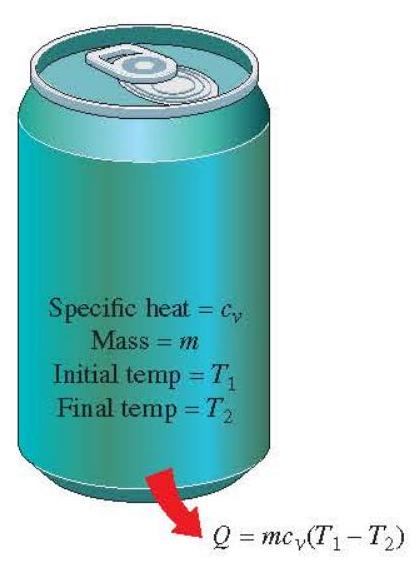
Figure 2-7 In the absence of any work interactions, the change in the energy content of a closed system is equal to the net heat transfer.
a specified location. The opposite of steady is unsteady or transient. Also, the term uniform implies no change with position throughout a surface or region at a specified time. These meanings are consistent with their everyday usage (steady job, uniform distribution, etc.). The total energy content of a control volume during steady-flow process remains constant ( (E{C V}=) constant). That is, the change in the total energy of the control volume during such a process is zero (\left(\Delta E{\mathrm{Cy}}=0\right)). Thus the amount of energy entering a control volume in all forms (heat, work, mass transfer) for a steady-flow process must be equal to the amount of energy leaving it. In rate form, it is expressed as (\dot{E}{\text {in }}=\dot{E}{\text {out }}).
The amount of mass flowing through a cross section of a flow device per unit time is called the mass flow rate, and is denoted by (\dot{m}). A fluid may flow in and out of a control volume through pipes or ducts. The mass flow rate of a fluid flowing in a pipe or duct is proportional to the cross-sectional area (A{c}) of the pipe or duct, the density (\rho), and the velocity (V) of the fluid. The flow of a fluid through a pipe or duct can often be approximated to be one dimensional. That is, the properties can be assumed to vary in one direction only (the direction of flow). As a result, all properties are assumed to be uniform at any cross section normal to the flow direction, and the properties are assumed to have bulk average values over the entire cross section. Under the one-dimensional flow approximation, the mass flow rate of a fluid flowing in a pipe or duct can be expressed as (Fig. 2-8)
[
\dot{m}=\rho V A{c} \quad(\mathrm{~kg} / \mathrm{s})
]
The volume of a fluid flowing through a pipe or duct per unit time is called the volume flow rate (\dot{V}), and is expressed as
[
\dot{V}=V A_{c}=\frac{\dot{m}}{\rho} \quad\left(\mathrm{~m}^{3} / \mathrm{s}\right)
]
Note that the mass flow rate of a fluid through a pipe or duct remains constant during steady flow. This is not the case for the volume flow rate, however, unless the density of the fluid remains constant.
For a steady-flow system with one inlet and one exit, the rate of mass flow into the control volume must be equal to the rate of mass flow out of it. That is, (\dot{m}{\text {in }}=\dot{m}{\text {out }}=\dot{m}). When the changes in kinetic and potential energies are negligible, which is usually the case, and there is no work interaction, the energy balance for such a steady-flow system reduces to (Fig. 2-9)
[
\dot{Q}=\dot{m} \Delta h=\dot{m} c_{p} \Delta T \quad(\mathrm{~kW})
]
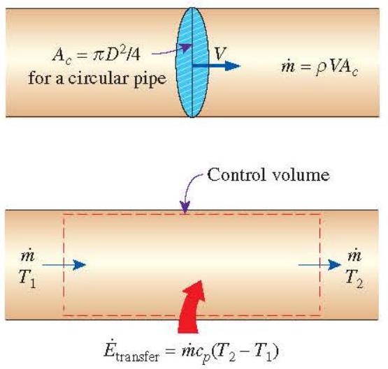
Figure 2-8 The mass flow rate of a fluid at a cross section is equal to the product of the fluid density, average fluid velocity, and the cross-sectional area.
Figure 2-9 Under steady conditions, the net rate of energy transfer to a fluid in a control volume is equal to the rate of increase in the energy of the fluid stream flowing through the control volume.
where (\dot{Q}) is the rate of net heat transfer into or out of the control volume. This is the form of the energy balance relation that we will use most often for steady-flow systems.
EXAMPLE 2-1 A house has an electric heating system that consists of a (250-\mathrm{W}) fan and an electric resistance heating element placed in a duct (Fig. 2-10). Air flows steadily through the duct at a rate of (0.5 \mathrm{~kg} / \mathrm{s}) and of a House experiences a temperature rise of (7^{\circ} \mathrm{C}). The rate of heat loss from the air in the duct is estimated to be 400 W . Determine the power rating of the electric resistance heating element.
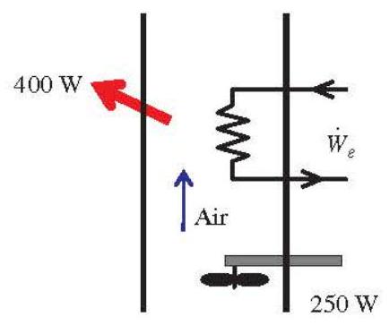
Figure 2-10 Schematic for Example 2-1.
SOLUTION Air is considered as an ideal gas and constant specific heats at room temperature can be used for air. The specific heat of air at room temperature is (c{p}=1.005 \mathrm{~kJ} / \mathrm{kg} \cdot{ }^{\circ} \mathrm{C}) (Table A-1). We take the heating duct as the system. This is a control volume since mass crosses the system boundary during the process. We observe that this is a steady-flow process since there is no change with time at any point and thus (\Delta m{\mathrm{CV}}=0) and (\Delta E{\mathrm{CV}}=0). Also, there is only one inlet and one exit and thus (\dot{m}{1}=\dot{m}{2}=\dot{m}). The energy balance for this steady-flow system can be expressed in the rate form as
[
\begin{aligned}
\dot{E}{\text {in }} & =\dot{E}{\text {out }} \
\dot{W}{e, \text { in }}+\dot{W}{\text {fan,in }}+\dot{m} h{1} & =\dot{Q}{\text {out }}+\dot{m} h{2} \
\dot{W}{e, \text { in }} & =\dot{Q}{\text {out }}-\dot{W}{\text {fan }, \text { in }}+\dot{m}\left(h{2}-h{1}\right) \
\dot{W}{e, \text { in }} & =\dot{Q}{\text {out }}-\dot{W}{\text {fan,in }}+\dot{m} c_{p} \Delta T
\end{aligned}
]
Substituting, the power rating of the heating element is determined to be
[
\dot{W}_{e, \text { in }}=(0.400 \mathrm{~kW})-(0.250 \mathrm{~kW})+(0.5 \mathrm{~kg} / \mathrm{s})\left(1.005 \mathrm{~kJ} / \mathrm{kg} \cdot{ }^{\circ} \mathrm{C}\right)\left(7^{\circ} \mathrm{C}\right)=\mathbf{3 . 6 7} \mathbf{~ k W}
]
Saturation Temperature and Saturation Pressure
Water starts to boil at (100^{\circ} \mathrm{C}). Strictly speaking, the statement "water boils at (100^{\circ} \mathrm{C}) " is incorrect. The correct statement is "water boils at (100^{\circ} \mathrm{C}) at 1 atm pressure." At 500 kPa pressure, water boils at (151.8^{\circ} \mathrm{C}). That is, the temperature at which water starts boiling depends on the pressure; therefore, if the pressure is fixed, so is the boiling temperature.
At a given pressure, the temperature at which a pure substance changes phase is called the saturation temperature (T{\text {sat }}). Likewise, at a given temperature, the pressure at which a pure substance changes phase is called the saturation pressure (P{\text {sat }}). At a pressure of 101.3 kPa , (T{\text {sat }}) is (100^{\circ} \mathrm{C}). Conversely, at a temperature of (100^{\circ} \mathrm{C}, P{\text {sat }}) is 101.3 kPa .
Saturation tables that list the saturation pressure against the temperature (or the saturation temperature against the pressure) are available for practically all substances. A partial listing of such a table is given in Table 2-1 for water. This table indicates that the pressure of
TABLE 2-1 Saturation (Boiling) Pressure of Water at Various Temperatures
\begin{tabular}{cc}
\hline & \begin{tabular}{l}
Saturation Pressure \
(P_{\text {stt }}, \mathrm{kPa})
\end{tabular} \
\hline-10 & 0.260 \
-5 & 0.403 \
0 & 0.611 \
5 & 0.872 \
10 & 1.23 \
15 & 1.71 \
20 & 2.34 \
25 & 3.17 \
30 & 4.25 \
40 & 7.38 \
50 & 12.35 \
100 & (101.3(1 \mathrm{~atm})) \
150 & 475.8 \
200 & 1554 \
250 & 3973 \
300 & 8581 \
\hline
\end{tabular}
water changing phase (boiling or condensing) at (25^{\circ} \mathrm{C}) must be 3.17 kPa , and the pressure of water must be maintained at 3976 kPa (about 40 atm ) to have it boil at (250^{\circ} \mathrm{C}). Also, water can be frozen by dropping its pressure below 0.61 kPa .
It takes a large amount of energy to melt a solid or vaporize a liquid. The amount of energy absorbed or released during a phase-change process is called the latent heat. More specifically, the amount of energy absorbed during melting is called the latent heat of fusion and is equivalent to the amount of energy released during freezing. Similarly, the amount of energy absorbed during vaporization is called the latent heat of vaporization and is equivalent to the energy released during condensation. The magnitudes of the latent heats depend on the temperature or pressure at which the phase change occurs. At 1 atm pressure, the latent heat of fusion of water is (333.7 \mathrm{~kJ} / \mathrm{kg}) and the latent heat of vaporization is (2256.5 \mathrm{~kJ} / \mathrm{kg}).
During a phase-change process, pressure and temperature are obviously dependent properties, and there is a definite relation between them, that is, (T{\text {sat }}=f\left(P{\text {sat }}\right)). A plot of (T{\text {sat }}) versus (P{\text {sap }}) such as the one given for water in Fig. 2-11, is called a liquid-vapor saturation curve. A curve of this kind is the characteristic of all pure substances.
It is clear from Fig. 2-11 that (T{\text {sat }}) increases with (P{\text {sat }}). Thus, a substance at higher pressures boils at higher temperatures. In the kitchen, higher boiling temperatures mean shorter cooking times and energy savings. A beef stew, for example, may take 1 to 2 h to cook in a regular pan that operates at 1 atm pressure, but only 20 min in a pressure cooker operating at 3 atm absolute pressure (corresponding boiling temperature: (134^{\circ} \mathrm{C}) ).
The atmospheric pressure, and thus the boiling temperature of water, decreases with elevation. Therefore, it takes longer to cook at higher altitudes than it does at sea level (unless a pressure cooker is used). For example, the standard atmospheric pressure at an
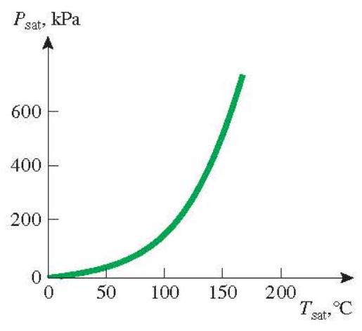
Figure 2-11 The liquid-vapor saturation curve of a pure substance (numerical values are for water).
elevation of 2000 m is 79.50 kPa , which corresponds to a boiling temperature of (93.3^{\circ} \mathrm{C}) as opposed to (100^{\circ} \mathrm{C}) at sea level (zero elevation). For each 1000 m increase in elevation, the boiling temperature drops by a little over (3^{\circ} \mathrm{C}).
3 HEAT TRANSFER
We define heat as the form of energy that can be transferred from one system to another as a result of temperature difference. A thermodynamic analysis is concerned with the amount of heat transfer as a system undergoes a process from one equilibrium state to another. The science that deals with the determination of the rates of such energy transfers is the heat transfer. The transfer of energy as heat is always from the higher-temperature medium to the lowertemperature one, and heat transfer stops when the two mediums reach the same temperature.
Heat can be transferred in three different modes: conduction, convection, and radiation. All modes of heat transfer require the existence of a temperature difference, and all modes are from the high-temperature medium to a lower-temperature one.
Conduction Heat Transfer
Conduction is the transfer of energy from the more energetic particles of substance to the adjacent less energetic ones as a result of interactions between the particles. Conduction can take place in solids, liquids, or gases. In gases and liquids, conduction is due to the collisions and diffusion of the molecules during their random motion. In solids, it is due to the combination of vibrations of the molecules in a lattice and the energy transport by free electrons. A cold canned drink in a warm room, for example, eventually warms up to the room temperature as a result of heat transfer from the room to the drink through the aluminum can by conduction.
The rate of heat conduction through a medium depends on the geometry of the medium, its thickness, and the material of the medium, as well as the temperature difference across the medium. We know that wrapping a hot water tank with glass wool (an insulating material) reduces the rate of heat loss from the tank. The thicker the insulation, the smaller the heat loss. We also know that a hot water tank loses heat at a higher rate when the temperature of the room housing the tank is lowered. Further, the larger the tank, the larger the surface area and thus the rate of heat loss.
Consider steady heat conduction through a large plane wall of thickness (\Delta x=L) and area (A), as shown in Fig. 2-12. The temperature difference across the wall is (\Delta T=T{2}-T{1}). Experiments have shown that the rate of heat transfer (\dot{Q}) through the wall is doubted when the
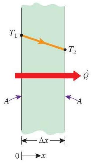
Figure 2-12 Heat conduction through a large plane wall.
temperature difference (\Delta T) across the wall or the area (A) normal to the direction of heat transfer is doubled, but is halved when the wall thickness (L) is doubled. Thus we conclude that the rate of heat conduction through a plane layer is proportional to the temperature difference across the layer and the heat transfer area, but is inversely proportional to the thickness of the layer. That is,
[
\dot{Q}{\text {cond }}=k A \frac{T{1}-T{2}}{\Delta x}=-k A \frac{\Delta T}{\Delta x} \quad(\mathrm{~kW})
]
where the constant of proportionality (k) is the thermal conductivity of the material, which is a measure of the ability of a material to conduct heat (Fig. 2-13). In the limiting case of (\Delta x \rightarrow 0), the equation above reduces to the differential form
[
\dot{Q}{\text {cond }}=-k A \frac{d T}{d x} \quad(\mathrm{~kW})
]
(a) Copper ((k=401 \mathrm{~W} / \mathrm{m} \cdot \mathrm{K}))
(b) Silicon ((k=148 \mathrm{~W} / \mathrm{m} \cdot \mathrm{K}))
Figure 2-13 The rate of heat conduction through a solid is directly proportional to its thermal conductivity.
which is called Fourier's law of heat conduction after J. Fourier, who expressed it first in his heat transfer text in 1822 . Here (d T / d x) is the temperature gradient, which is the slope of the temperature curve on a (T-x) diagram (the rate of change of (T) with (x) ), at location (x). The relation above indicates that the rate of heat conduction in a given direction is proportional to the temperature gradient in that direction. Heat is conducted in the direction of decreasing temperature, and the temperature gradient becomes negative when temperature decreases with increasing (x). The negative sign in Eq. (2-17) ensures that heat transfer in the positive (x) direction is a positive quantity.
The heat transfer area (A) is always normal to the direction of heat transfer. For heat loss through a (5-\mathrm{m})-long, (3-\mathrm{m})-high, and (25-\mathrm{cm})-thick wall, for example, the heat transfer area is (A=15 \mathrm{~m}^{2}). Note that the thickness of the wall has no effect on (A).
Thermal Conductivity
We can define specific heat (c{p}) as a measure of a material's ability to store thermal energy. For example, (c{p}=4.18 \mathrm{~kJ} / \mathrm{kg} \cdot{ }^{\circ} \mathrm{C}) for water and (c_{p}=0.45 \mathrm{~kJ} / \mathrm{kg} \cdot{ }^{\circ} \mathrm{C}) for iron at room temperature, which indicates that water can store almost 10 times the energy that iron can per unit mass. Likewise, the thermal conductivity (k) is a measure of a material's ability to conduct heat. For example, (k=0.607 \mathrm{~W} / \mathrm{m} \cdot \mathrm{K}) for water and (k=80.2 \mathrm{~W} / \mathrm{m} \cdot \mathrm{K}) for iron at room temperature, which indicates that iron conducts heat more than 100 times faster than water can. Thus we say that water is a poor heat conductor relative to iron, although water is an excellent medium to store thermal energy.
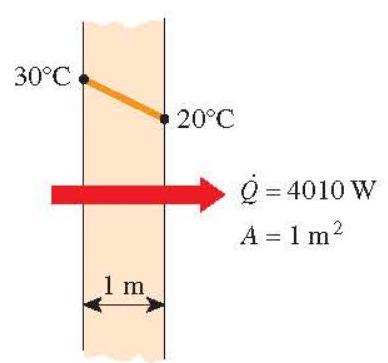
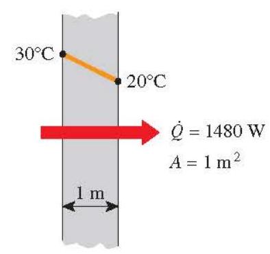
Equation (2-16) for the rate of conduction heat transfer under steady conditions can also be viewed as the defining equation for thermal conductivity. Thus the thermal conductivity of a material can be defined as the rate of heat transfer through a wnit thickness of the material per unit area per unit temperature difference. The thermal conductivity of a material is a measure of the ability of the material to conduct heat. A high value for thermal conductivity indicates that the material is a good heat conductor, and a low value indicates that the material is a poor heat conductor or insulator. The thermal conductivities of some common materials at room temperature are given in Table 2-2. The thermal conductivity of pure copper at room temperature is (k=401 \mathrm{~W} / \mathrm{m} \cdot \mathrm{K}), which indicates that a 1-m-thick copper wall will conduct heat at a rate of 401 W per (\mathrm{m}^{2}) area per K temperature difference across the wall. Note that materials such as copper and silver that are good electric conductors are also good heat conductors, and have high values of thermal conductivity. Materials such as rubber, wood, and styrofoam are poor conductors of heat and have low conductivity values.
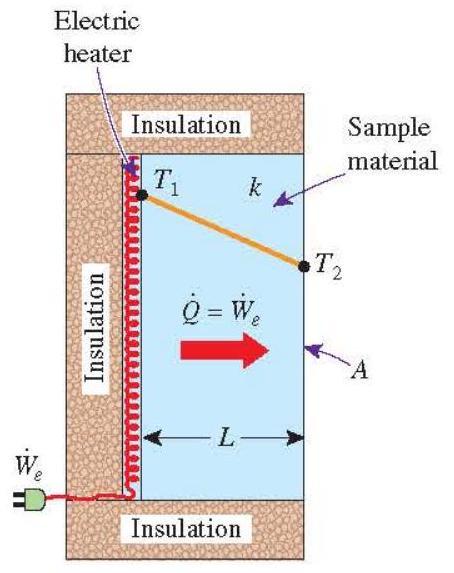
A layer of material of known thickness and area can be heated from one side by an electric resistance heater of known output. If the outer surfaces of the heater are well insulated, all the heat generated by the resistance heater will be transferred through the material whose conductivity is to be determined. Then measuring the two surface temperatures of the material when steady heat transfer is reached and substituting them into Eq. (2-16) together with other known quantities give the thermal conductivity (Fig. 2-14).
The thermal conductivities of materials vary over a wide range, as shown in Fig. 2-15. The thermal conductivities of gases such as air vary by a factor of (10^{4}) from those of pure metals such as copper. Note that pure crystals and metals have the highest thermal conductivities, and gases and insulating materials the lowest.
Temperature is a measure of the kinetic energies of the particles such as the molecules or atoms of a substance. In a liquid or gas, the kinetic energy of the molecules is due to their random translational motion as well as their vibrational and rotational motions. When two molecules possessing different kinetic energies collide, part of the kinetic energy of the more energetic (higher-temperature)molecule is transferred to the less energetic
TABLE 2-2 Thermal Conductivities of Some Materials at Room Temperature
\begin{tabular}{lc}
\hline Material & \begin{tabular}{c}
Thermal \
Conductivity (k), \
(\mathrm{W} / \mathrm{m} \cdot \mathrm{K}^{})
\end{tabular} \
\hline Diamond & 2300 \
Silver & 429 \
Copper & 401 \
Gold & 317 \
Aluminum & 237 \
Iron & 80.2 \
Mercury ((l)) & 8.54 \
Glass & 0.78 \
Brick & 0.72 \
Water ((l)) & 0.607 \
Human skin & 0.37 \
Wood (oak) & 0.17 \
Helium ((g)) & 0.152 \
Soft rubber & 0.13 \
Glass fiber & 0.043 \
Air ((g)) & 0.026 \
Urethane, rigid foam & 0.026 \
\hline
\end{tabular}
({ }^{}) Multiply by 0.5778 to convert to (\mathrm{Btu} / \mathrm{h} \cdot \mathrm{ft} \cdot{ }^{\circ} \mathrm{F}).
(lower-temperature)molecule, much the same as when two elastic balls of the same mass at different velocities collide, part of the kinetic energy of the faster ball is transferred to the slower one. The higher the temperature, the faster the molecules move and the higher the number of such collisions, and the better the heat transfer.
The kinetic theory of gases predicts and the experiments confirm that the thermal conductivity of gases is proportional to the square root of the thermodynamic temperature (T),
[
k=\frac{L}{A\left(T{1}-T{2}\right)} \dot{Q}
]
Figure 2-14 A simple experimental setup to determine the thermal conductivity of a material.
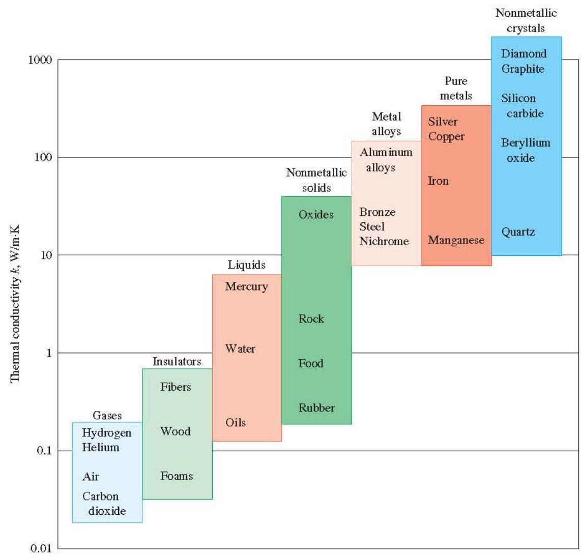
Figure 2-15 The range of thermal conductivity of various materials at room temperature.
and inversely proportional to the square root of the molar mass (M). Therefore, for a particular gas (fixed (M) ), the thermal conductivity increases with increasing temperature and at a fixed temperature the thermal conductivity decreases with increasing (M). For example, at affixed temperature of 1000 K , the thermal conductivity of helium ((M=4)) is (0.343 \mathrm{~W} / \mathrm{m} \cdot \mathrm{K}) and that of air ((M=29)) is (0.0667 \mathrm{~W} / \mathrm{m} \cdot \mathrm{K}), which is much lower than that of helium.
The mechanism of heat conduction in a liquid is complicated by the fact that the molecules are more closely spaced, and they exert a stronger intermolecular force field. The thermal conductivities of liquids usually lie between those of solids and gases. The thermal conductivity of a substance is normally highest in the solid phase and lowest in the gas phase. The thermal conductivity of liquids is generally insensitive to pressure except near the thermodynamic critical point. Unlike gases, the thermal conductivities of most liquids decrease with increasing temperature, with water being a notable exception. Like gases, the conductivity of liquids decreases with increasing molar mass. Liquid metals such as mercury and sodium have high thermal conductivities and are very suitable for use in applications where a high heat transfer rate to a liquid is desired, as in nuclear power plants.
In solids, heat conduction is due to two effects: the lattice vibrational waves induced by the vibrational motions of the molecules positioned at relatively fixed positions in a periodic manner called a lattice, and the energy transported via the free flow of electrons in the solid. The thermal conductivity of a solid is obtained by adding the lattice and electronic components. The relatively high thermal conductivities of pure metals are primarily due to
the electronic component. The lattice component of thermal conductivity strongly depends on the way the molecules are arranged. For example, diamond, which is a highly ordered crystalline solid, has the highest known thermal conductivity at room temperature.
Unlike metals, which are good electrical and heat conductors, crystalline solids such as diamond and semiconductors such as silicon are good heat conductors but poor electrical conductors. As a result, such materials find widespread use in the electronics industry. Despite their higher price, diamond heat sinks are used in the cooling of sensitive electronic components because of the excellent thermal conductivity of diamond. Silicon oils and gaskets are commonly used in the packaging of electronic components because they provide both good thermal contact and good electrical insulation.
Pure metals have high thermal conductivities, and one would think that metal alloys should also have high conductivities. One would expect an alloy made of two metals of thermal conductivities (k{1}) and (k{2}) to have a conductivity (k) between (k{1}) and (k{2}). But this turns out not to be the case. Even small amounts in a pure metal of "foreign" molecules that are good conductors themselves seriously disrupt the transfer of heat in that metal. For example, the thermal conductivity of steel containing just 1 percent of chrome is (62 \mathrm{~W} / \mathrm{m} \cdot \mathrm{K}), while the thermal conductivities of iron and chromium are 83 and (95 \mathrm{~W} / \mathrm{m} \cdot \mathrm{K}), respectively.
The thermal conductivities of materials vary with temperature. The variation of thermal conductivity over certain temperature ranges is negligible for some materials, but significant for others, as shown in Fig. 2-16. The thermal conductivities of certain solids
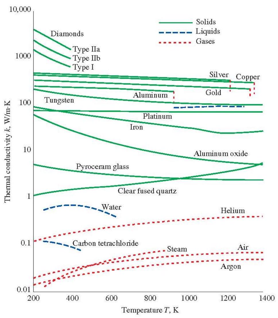
Figure 2-16 The variation of the thermal conductivity of various solids, liquids, and gases with temperature.
exhibit dramatic increases at temperatures near absolute zero, when these solids become superconductors. For example, the conductivity of copper reaches a maximum value of about (20,000 \mathrm{~W} / \mathrm{m} \cdot \mathrm{K}) at 20 K , which is about 50 times the conductivity at room temperature.
The temperature dependence of thermal conductivity causes considerable complexity in conduction analysis. Therefore, it is common practice to evaluate the thermal conductivity (k) at the average temperature and treat it as a constant in calculations. In heat transfer analysis, a material is normally assumed to be isotropic; that is, to have uniform properties in all directions. This assumption is realistic for most materials, except those that exhibit different structural characteristics in different directions, such as laminated composite materials and wood. The thermal conductivity of wood across the grain, for example, is different than that parallel to the grain.
EXAMPLE 2-2 The east wall of an electrically heated home is 15 ft long, 8 ft high, and 1 ft thick, and is made of brick Heat Loss Through a Wall whose thermal conductivity is (k=0.42 \mathrm{Btu} / \mathrm{h} \cdot \mathrm{ft} \cdot{ }^{\circ} \mathrm{F}). On a certain winter night, the temperatures of the inner and the outer surfaces of the wall are measured to be at about (65^{\circ} \mathrm{F}) and (33^{\circ} \mathrm{F}), respectively, for a period of 10 h (Fig. 2-17). Determine (a) the rate of heat loss through the wall that night and (b) the cost of that heat loss to the home owner if the cost of electricity is (\$ 0.12 / \mathrm{kWh}).
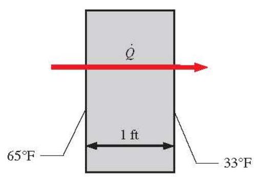
Figure 2-17 Schematic for Example 2-2.
SOLUTION (a) Noting that the heat transfer through the wall is by conduction and the surface area of the wall is (A=15 \mathrm{ft} \times 8 \mathrm{ft}=120 \mathrm{ft}^{2}), the steady rate of heat transfer through the wall can be determined from
[
\dot{Q}=k A \frac{T{1}-T{2}}{L}=\left(0.42 \mathrm{Btu} / \mathrm{h} \cdot \mathrm{ft} \cdot{ }^{\circ} \mathrm{F}\right)\left(120 \mathrm{ft}^{2}\right) \frac{(65-33)^{\circ} \mathrm{F}}{1 \mathrm{ft}}=1613 \mathrm{Btu} / \mathrm{h}
]
or 0.473 kW since (1 \mathrm{~kW}=3412 \mathrm{Btu} / \mathrm{h}).
(b) The amount of heat lost during a (10-\mathrm{h}) period and its cost are
[
\begin{gathered}
Q=\dot{Q} \Delta t=(0.473 \mathrm{~kW})(10 \mathrm{~h})=4.73 \mathrm{kWh} \
\text { Cost }=\text { Amount of energy } \times \text { Unit cost of energy }=(4.73 \mathrm{kWh})(\$ 0.12 \mathrm{kWh})=\$ 0.57
\end{gathered}
]
Therefore, the cost of the heat loss through the wall to the home owner that night is (\$ 0.57).
Convection Heat Transfer
Convection is the mode of energy transfer between a solid surface and the adjacent liquid or gas that is in motion, and it involves the combined effects of conduction and fluid motion. The faster the fluid motion, the greater the convection heat transfer. In the absence of any bulk fluid motion, heat transfer between solid surface and the adjacent
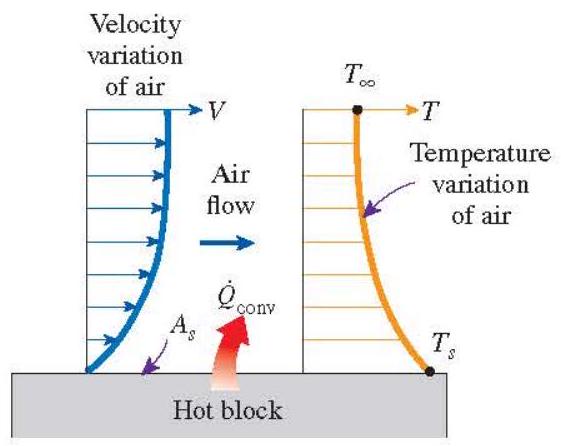
Figure 2-18 Heat transfer from a hot surface to air by convection.
fluid is by pure conduction. The presence of bulk motion of the fluid enhances the heat transfer between the solid surface and the fluid, but it also complicates the determination of heat transfer rates.
Consider the cooling of a hot block by blowing cool air over its top surface (Fig. 2-18). Heat is first transferred to the air layer adjacent to the block by conduction. This heat is then carried away from the surface by convection, that is, by the combined effects of conduction within the air that is due to random motion of air molecules and the bulk or macroscopic motion of the air that removes the heated air near the surface and replaces it by the cooler air.
Convection is called forced convection if the fluid is forced to flow over the surface by external means such as a fan, pump, or the wind. In contrast, convection is called natural (or free) convection if the fluid motion is caused by buoyancy forces that are induced by density differences due to the variation of temperature in the fluid (Fig. 2-19). For example, in the absence of a fan, heat transfer from the surface of the hot block in Fig. 2-18 is by natural convection since any motion in the air in this case is due to the rise of the warmer (and thus lighter) air near the surface and the fall of the cooler (and thus heavier) air to fill its place. Heat transfer between the block and the surrounding air is by conduction if the temperature difference between the air and the block is not large enough to overcome the resistance of air to movement and thus to initiate natural convection currents.
Heat transfer processes that involve change of phase of a fluid are also considered to be convection because of the fluid motion induced during the process, such as the rise of the vapor bubbles during boiling or the fall of the liquid droplets during condensation.
Despite the complexity of convection, the rate of convection heat transfer is observed to be proportional to the temperature difference, and is conveniently expressed by Newton's law of cooling as
[
\dot{Q}{\text {conv }}=h A{s}\left(T{s}-T{\infty}\right) \quad(\mathrm{kW})
]
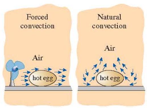
Figure 2-19 The cooling of a boiled egg by forced and natural convection.
TABLE 2-3 Typical Values of Convection Heat Transfer Coefficient
\begin{tabular}{lc}
\hline & \begin{tabular}{l}
Heat Transfer \
Coefficient (h), \
(\mathrm{W} / \mathrm{m}^{2} \cdot \mathrm{~K}^{})
\end{tabular} \
\hline Type of Convection & (2-25) \
Free convection of gases & (10-1000) \
Forced convection of gases & (25-250) \
Forced convection of liquids & (50-20,000) \
Boiling and condensation & (2500-100,000) \
\hline
\end{tabular}
({ }^{}) Multiply by 0.176 to convert to (\mathrm{Btu} / \mathrm{h} \cdot \mathrm{ft}^{2} \cdot{ }^{\circ} \mathrm{F}).
where (h) is the convection heat transfer coefficient in (\mathrm{W} / \mathrm{m}^{2} \cdot \mathrm{~K}) or Btu (/ \mathrm{h} \cdot \mathrm{ft}^{2} \cdot{ }^{\circ} \mathrm{F}, A{s}) is the surface area through which convection heat transfer takes place, (T{s}) is the surface temperature, and (T_{\infty}) is the temperature of the fluid sufficiently far from the surface. Note that at the surface, the fluid temperature equals the surface temperature of the solid.
The convection heat transfer coefficient (h) is not a property of the fluid. It is an experimentally determined parameter whose value depends on all the variables influencing convection such as the surface geometry, the nature of fluid motion, the properties of the fluid, and the bulk fluid velocity. Typical values of (h) are given in Table 2-3.
Radiation Heat Transfer
Radiation is the energy emitted by matter in the form of electromagnetic waves (or photons) as a result of the changes in the electronic configurations of the atoms or molecules. Unlike conduction and convection, the transfer of heat by radiation does not require the presence of an intervening medium. In fact, heat transfer by radiation is fastest (at the speed of light) and it suffers no attenuation in a vacuum. This is how the energy of the sun reaches the earth.
In heat transfer studies we are interested in thermal radiation, which is the form of radiation emitted by bodies because of their temperature. It differs from other forms of electromagnetic radiation such as x rays, gamma rays, microwaves, radio waves, and television waves that are not related to temperature. All bodies at a temperature above absolute zero emit thermal radiation.
Radiation is a volumetric phenomenon, and all solids, liquids, and gases emit, absorb, or transmit radiation to varying degrees. However, radiation is usually considered to be a surface phenomenon for solids that are opaque to thermal radiation such as metals, wood, and rocks since the radiation emitted by the interior regions of such material can never reach the surface, and the radiation incident on such bodies is usually absorbed within a few micrometers from the surface.
The maximum rate of radiation that can be emitted from a surface at a thermodynamic temperature (T{s}) (in K or R ) is given by the Stefan-Boltzmann law as
[
\dot{Q}{\text {emitmax }}=\sigma A{s} T{s}^{4} \quad(\mathrm{~kW})
]
where (\sigma=5.670 \times 10^{-8} \mathrm{~W} / \mathrm{m}^{2} \cdot \mathrm{~K}^{4}) or (0.1714 \times 10^{-8} \mathrm{Btu} / \mathrm{h} \cdot \mathrm{ft}^{2} \cdot \mathrm{R}^{4}) is the Stefan-Boltzmann constant. The idealized surface that emits radiation at this maximum rate is called a blackbody, and the radiation emitted by a blackbody is called blackbody radiation (Fig. 2-20). The radiation emitted by all real surfaces is less than the radiation emitted by a blackbody at the same temperature, and is expressed as
[
\dot{Q}{\text {emit }}=\varepsilon \sigma A{s} T_{s}^{4}
]
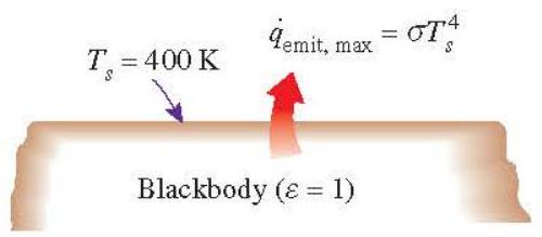
Figure 2-20 Blackbody radiation represents the maximum amount of radiation that can be emitted from a surface at a specified temperature.
where (\varepsilon) is the emissivity of the surface. The property emissivity, whose value is in the range (0<\varepsilon<1), is a measure of how closely a surface approximates blackbody for which (\varepsilon=1). The emissivities of some surfaces are given in Table 2-4.
Another important radiation property of a surface is its absorptivity (\alpha), which is the fraction of the radiation energy incident on a surface that is absorbed by the surface. Like emissivity, its value is in the range (0<\alpha<1). A blackbody absorbs the entire radiation incident on it. That is, a blackbody is a perfect absorber ((\alpha=1)) as it is a perfect emitter.
In general, both (\varepsilon) and (\alpha) of a surface depend on the temperature and the wavelength of the radiation. Kirchhoff's law of radiation states that the emissivity and the absorptivity of a surface at a given temperature and wavelength are equal. In many practical applications, the surface temperature and the temperature of the source of incident radiation are of the same order of magnitude, and the average absorptivity of a surface is taken to be equal to its average emissivity. The rate at which a surface absorbs radiation is determined from (Fig. 2-21)
[
\dot{Q}{\text {absorbed }}=\alpha \dot{Q}{\text {incident }} \quad(\mathrm{kW})
]
TABLE 2-4 Emissivities of Some Materials at 300 K
\begin{tabular}{ll}
\hline Material & Emissivity (\varepsilon) \
\hline Aluminum foil & 0.07 \
Anodized aluminum & 0.82 \
Polished copper & 0.03 \
Polished gold & 0.03 \
Polished silver & 0.02 \
Polished stainless steel & 0.17 \
Black paint & 0.98 \
White paint & 0.90 \
White paper & (0.92-0.97) \
Asphalt pavement & (0.85-0.93) \
Red brick & (0.93-0.96) \
Human skin & 0.95 \
Wood & (0.82-0.92) \
Soil & (0.93-0.96) \
Water & 0.96 \
Vegetation & (0.92-0.96) \
\hline
\end{tabular}
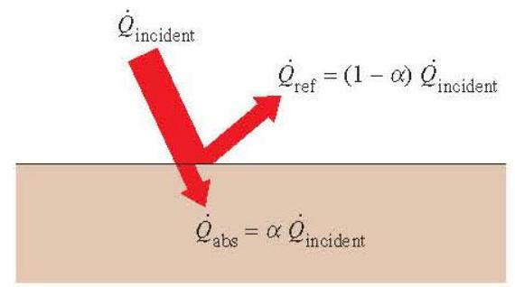
Figure 2-21 The absorption of radiation incident on an opaque surface of absorptivity (\alpha)
where (\dot{Q}_{\text {incident }}) is the rate at which radiation is incident on the surface and (\alpha) is the absorptivity of the surface. For opaque (nontransparent) surfaces, the portion of incident radiation not absorbed by the surface is reflected back.
The difference between the rates of radiation emitted by the surface and the radiation absorbed is the net radiation heat transfer. If the rate of radiation absorption is greater than the rate of radiation emission, the surface is said to be gaining energy by radiation. Otherwise, the surface is said to be losing energy by radiation. In general, the determination of the net rate of heat transfer by radiation between two surfaces is a complicated matter since it depends on the properties of the surfaces, their orientation relative to each other, and the interaction of the medium between the surfaces with radiation.
When a surface of emissivity (\varepsilon) and surface area (A{s}) at a thermodynamic temperature (T{s}) are completely enclosed by a much larger (or black) surface at thermodynamic temperature (T{\text {surf }}) separated by a gas (such as air) that does not intervene with radiation, the net rate of radiation heat transfer between these two surfaces is given by (Fig. 2-22)
[
\dot{Q}{\mathrm{rad}}=\varepsilon \sigma A{s}\left(T{s}^{4}-T_{\text {surr }}^{4}\right) \quad(\mathrm{kW})
]
In this special case, the emissivity and the surface area of the surrounding surface do not have any effect on the net radiation heat transfer.
Radiation heat transfer to or from a surface surrounded by a gas such as air occurs parallel to conduction (or convection, if there is bulk gas motion) between the surface and the gas. Thus the total heat transfer is determined by adding the contributions of both heat transfer mechanisms. For simplicity and convenience, this is often done by defining a combined heat transfer coefficient (h_{\text {combined }}) that includes the effects of both convection
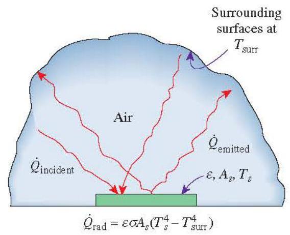
Figure 2-22 Radiation heat transfer between a surface and the surfaces surrounding it.
and radiation. Then the total heat transfer rate to or from a surface by convection and radiation is expressed as
[
\begin{aligned}
\dot{Q}{\text {total }} & =\dot{Q}{\text {conv }}+\dot{Q}{\text {rad }}=h{\text {conv }} A{s}\left(T{s}-T{\infty}\right)+\varepsilon \sigma A{s}\left(T{s}^{4}-T{\text {surr }}^{4}\right) \
\dot{Q}{\text {total }} & =h{\text {combined }} A{s}\left(T{s}-T{\infty}\right) \
h{\text {combined }} & =h{\text {conv }}+h{\text {rad }}=h{\text {conv }}+\varepsilon \sigma\left(T{s}+T{\text {surr }}\right)\left(T{s}^{2}+T_{\text {surr }}^{2}\right)
\end{aligned}
]
Note that the combined heat transfer coefficient is essentially a convection heat transfer coefficient modified to include the effects of radiation.
Radiation is usually significant relative to conduction or natural convection, but negligible relative to forced convection. Thus radiation in forced convection applications is usually disregarded, especially when the surfaces involved have low emissivities and low to moderate temperatures.
EXAMPLE 2-3 Consider steady heat transfer between two large parallel plates at constant temperatures of (T{1}=320 \mathrm{~K}) Heat Transfer Between the Two Plates and (T{2}=276 \mathrm{~K}) that are (L=3 \mathrm{~cm}) apart (Fig. 2-23). Assuming the surfaces to be black (emissivity (\varepsilon=1) ), determine the rate of heat transfer between the plates per unit surface area assuming the gap between the plates is (a) filled with atmospheric air ( (k{\text {dir }}=0.02551 \mathrm{~W} / \mathrm{m} \cdot \mathrm{K}) ), (b) evacuated, (c) filled with fiberglass insulation ( (k{\text {ins }}=0.036 \mathrm{~W} / \mathrm{m} \cdot \mathrm{K}) ), and (d) filled with superinsulation having an apparent thermal conductivity of (0.00015 \mathrm{~W} / \mathrm{m} \cdot \mathrm{K}).
SOLUTION (a) Disregarding any natural convection currents, the rates of conduction and radiation heat transfer are
[
\begin{aligned}
\dot{Q}{\text {cond }} & =k A \frac{T{1}-T{2}}{L}=\left(0.02551 \mathrm{~W} / \mathrm{m}^{2} \cdot \mathrm{~K}\right)\left(1 \mathrm{~m}^{2}\right) \frac{(320-276) \mathrm{K}}{0.03 \mathrm{~m}}=37.4 \mathrm{~W} \
\dot{Q}{\text {rad }} & =\varepsilon \sigma A{s}\left(T{1}^{4}-T{2}^{4}\right) \
& =1\left(5.67 \times 10^{-8} \mathrm{~W} / \mathrm{m}^{2} \cdot \mathrm{~K}^{4}\right)\left(1 \mathrm{~m}^{2}\right)\left[(320 \mathrm{~K})^{4}-(276 \mathrm{~K})^{4}\right] \
& =265.5 \mathrm{~W} \
\dot{Q}{\text {total }} & =\dot{Q}{\text {cond }}+\dot{Q}{\text {rdd }}=37.4+265.5=\mathbf{3 0 3} \mathrm{W}
\end{aligned}
]
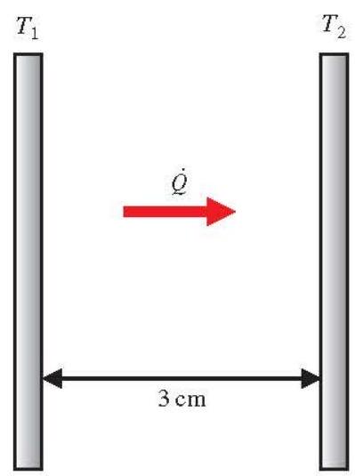
Figure 2-23 Schematic for Example 2-3.
(b) When the air space between the plates is evacuated, there will be radiation heat transfer only. Therefore,
[
\dot{Q}{\text {total }}=\dot{Q}{\text {rad }}=266 \mathrm{~W}
]
(c) In this case, there will be conduction heat transfer through the fiberglass insulation only,
[
\dot{Q}{\text {total }}=\dot{Q}{\text {cond }}=k A \frac{T{1}-T{2}}{L}=(0.036 \mathrm{~W} / \mathrm{m} \cdot \mathrm{~K})\left(1 \mathrm{~m}^{2}\right) \frac{(320-276) \mathrm{K}}{0.03 \mathrm{~m}}=\mathbf{5 2 . 8} \mathrm{W}
]
(d) In the case of superinsulation, the rate of heat transfer will be
[
\dot{Q}{\text {total }}=\dot{Q}{\text {cond }}=k A \frac{T{1}-T{2}}{L}=(0.00015 \mathrm{~W} / \mathrm{m} \cdot \mathrm{~K})\left(1 \mathrm{~m}^{2}\right) \frac{(320-276) \mathrm{K}}{0.03 \mathrm{~m}}=0.22 \mathrm{~W}
]
Note that superinsulators are very effective in reducing heat transfer between the plates.
4 FLUID MECHANICS
Mechanics is the oldest physical science that deals with both stationary and moving bodies under the influence of forces. The branch of mechanics that deals with bodies at rest is called statics, while the branch that deals with bodies in motion is called dynamics. The subcategory fluid mechanics is defined as the science that deals with the behavior of fluids at rest (fluid statics) or in motion (fluid dynamics), and the interaction of fluids with solids or other fluids at the boundaries.
Fluid mechanics itself is also divided into several categories. The study of the motion of fluids that can be approximated as incompressible (such as liquids, especially water, and gases at low speeds) is usually referred to as hydrodynamics. A subcategory of hydrodynamics is hydraulics, which deals with liquid flows in pipes and open channels. Gas dynamics deals with the flow of fluids that undergo significant density changes, such as the flow of gases through nozzles at high speeds. The category aerodynamics deals with the flow of gases (especially air) over bodies such as aircraft, rockets, and automobiles at high or low speeds. Some other specialized categories such as meteorology, oceanography, and hydrology deal with naturally occurring flows.
You will recall from physics that a substance exists in three primary phases: solid, liquid, and gas. (At very high temperatures, it also exists as plasma.) A substance in the liquid or gas phase is referred to as a fluid. Distinction between a solid and a fluid is made on the basis of the substance's ability to resist an applied shear (or tangential) stress that tends to change its shape. A solid can resist an applied shear stress by deforming, whereas a fluid deforms continuously under the influence of a shear stress, no matter how small. In solids, stress is proportional to strain, but in fluids, stress is proportional to strain rate. When a constant shear force is applied, a solid eventually stops deforming at some fixed strain angle, whereas a fluid never stops deforming and approaches a constant rate of strain.
In a liquid, groups of molecules can move relative to each other, but the volume remains relatively constant because of the strong cohesive forces between the molecules. As a result, a liquid takes the shape of the container it is in, and it forms a free surface in a larger container in a gravitational field. A gas, on the other hand, expands until it encounters the walls of the container and fills the entire available space. This is because the gas molecules are widely spaced, and the cohesive forces between them are very small. Unlike liquids, a gas in an open container cannot form a free surface (Fig. 2-24).
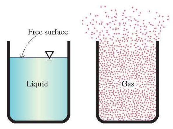
Figure 2-24 Unlike a liquid, a gas does not form a free surface, and it expands to fill the entire available space.
Viscosity
When two solid bodies in contact move relative to each other, a friction force develops at the contact surface in the direction opposite to motion. To move a table on the floor, for example, we have to apply a force to the table in the horizontal direction large enough to overcome the friction force. The magnitude of the force needed to move the table depends on the friction coefficient between the table legs and the floor.
The situation is similar when a fluid moves relative to a solid or when two fluids move relative to each other. We move with relative ease in air, but not so in water. Moving in oil would be even more difficult, as can be observed by the slower downward motion of a glass ball dropped in a tube filled with oil. It appears that there is a property that represents the internal resistance of a fluid to motion or the "fluidity", and that property is the viscosity. The force a flowing fluid exerts on a body in the flow direction is called the drag force, and the magnitude of this force depends, in part, on viscosity (Fig. 2-25).
Fluids for which the rate of deformation is linearly proportional to the shear stress are called Newtonian fluids after Sir Isaac Newton, who expressed it first in 1687. Most common fluids such as water, air, gasoline, and oils are Newtonian fluids. Blood and liquid plastics are examples of non-Newtonian fluids.
In one-dimensional shear flow of Newtonian fluids, shear stress can be expressed by the linear relationship
[
\tau=\mu \frac{d u}{d y} \quad\left(\mathrm{~N} / \mathrm{m}^{2}\right)
]
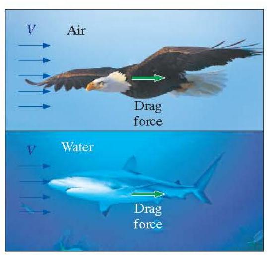
Figure 2-25 A fluid moving relative to a body exerts a drag force on the body, partly because of friction caused by viscosity. (© Getty RF.)
where the constant of proportionality (\mu) is called the coefficient of viscosity or the dynamic (or absolute) viscosity of the fluid, whose unit is (\mathrm{kg} / \mathrm{m} \cdot \mathrm{s}), or equivalently, (\mathrm{N} \cdot \mathrm{s} / \mathrm{m}^{2}) (or Pa.s where Pa is the pressure unit pascal). A common viscosity unit is poise, which is equivalent to (0.1 \mathrm{~Pa} \cdot \mathrm{~s}) (or centipoise, which is one-hundredth of a poise). The viscosity of water at (20^{\circ} \mathrm{C}) is 1.002 centipoise, and thus the unit centipoise serves as a useful reference.
In fluid mechanics and heat transfer, the ratio of dynamic viscosity to density appears frequently. For convenience, this ratio is given the name kinematic viscosity (v) and is expressed as (v=\mu / \rho). Two common units of kinematic viscosity are (\mathrm{m}^{2} / \mathrm{s}) and stoke ((1) stoke (=) (\left.1 \mathrm{~cm}^{2} / \mathrm{s}=0.0001 \mathrm{~m}^{2} / \mathrm{s}\right)).
In general, the viscosity of a fluid depends on both temperature and pressure, although the dependence on pressure is rather weak. For liquids, both the dynamic and kinematic viscosities are practically independent of pressure, and any small variation with pressure is usually disregarded, except at extremely high pressures. For gases, this is also the case for dynamic viscosity (at low to moderate pressures), but not for kinematic viscosity since the density of a gas is proportional to its pressure.
The viscosity of a fluid is a measure of its "resistance to deformation." Viscosity is due to the internal frictional force that develops between different layers of fluids as they are forced to move relative to each other.
The viscosity of a fluid is directly related to the pumping power needed to transport a fluid in a pipe or to move a body (such as a car in air or a submarine in the sea) through a fluid. Viscosity is caused by the cohesive forces between the molecules in liquids and by the molecular collisions in gases, and it varies greatly with temperature. The viscosity of liquids decreases with temperature, whereas the viscosity of gases increases with temperature (Fig. 2-26). This is because in a liquid the molecules possess more energy at higher temperatures, and they can oppose the large cohesive intermolecular forces more strongly. As a result, the energized liquid molecules can move more freely.
In a gas, on the other hand, the intermolecular forces are negligible, and the gas molecules at high temperatures move randomly at higher velocities. This results in more molecular collisions per unit volume per unit time and therefore in greater resistance to flow. The kinetic theory of gases predicts the viscosity of gases to be proportional to the square root of temperature.
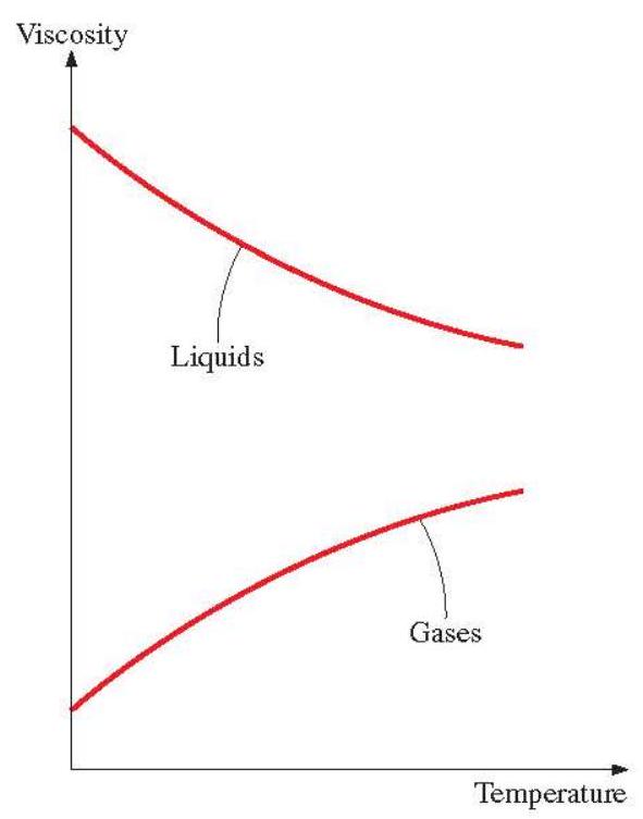
Figure 2-26 The viscosity of liquids decreases and the viscosity of gases increases with temperature.
TABLE 2-5 Dynamic Viscosity of Some Fluids at 1 atm and (20^{\circ}) ( (Unless 0 therwise Stated)
\begin{tabular}{lc}
\hline Fluid & \begin{tabular}{c}
Dynamic Viscosity (\mu), \
(\mathrm{kg} / \mathrm{m} \cdot \mathrm{s})
\end{tabular} \
\hline Glycerin: & \
(-20^{\circ} \mathrm{C}) & 134.0 \
(0^{\circ} \mathrm{C}) & 10.5 \
(20^{\circ} \mathrm{C}) & 1.52 \
(40^{\circ} \mathrm{C}) & 0.31 \
Engine oil: & \
SAE 10 W & 0.10 \
SAE 10 W30 & 0.17 \
SAE 30 & 0.29 \
SAE 50 & 0.86 \
Mercury & 0.0015 \
Ethyl alcohol & 0.0012 \
Water: & \
(\quad 0^{\circ} \mathrm{C}) & 0.0018 \
(20^{\circ} \mathrm{C}) & 0.0010 \
(100^{\circ} \mathrm{C}) (liquid) & 0.00028 \
(100^{\circ} \mathrm{C}) (vapor) & 0.000012 \
Blood, (37^{\circ} \mathrm{C}) & 0.00040 \
Gasoline & 0.00029 \
Ammonia & 0.00015 \
Air & 0.000018 \
Hydrogen, (0^{\circ} \mathrm{C}) & 0.0000088 \
\hline
\end{tabular}
The viscosities of some fluids at room temperature are listed in Table 2-5. They are plotted against temperature in Fig. 2-27. Note that the viscosities of different fluids differ by several orders of magnitude. Also note that it is more difficult to move an object in a higherviscosity fluid such as engine oil than it is in a lower-viscosity fluid such as water. Liquids, in general, are much more viscous than gases.
Pressure Drop in Fluid Flow in Pipes
The pressure loss and head loss for all types of internal flows (laminar or turbulent, in circular or noncircular pipes, smooth or rough surfaces) are expressed as (Fig. 2-28)
[
\begin{gathered}
\Delta P{L}=f \frac{L}{D} \frac{\rho V^{2}}{2} \
h{L}=\frac{\Delta P_{L}}{\rho g}=f \frac{L}{D} \frac{V^{2}}{2 g}
\end{gathered}
]
where (\rho) is the density, (V) is average velocity of fluid, (L) is the pipe length, (g) is gravitational acceleration, (\rho V^{2} / 2) is the dynamic pressure, and the dimensionless quantity (f) is the friction factor.
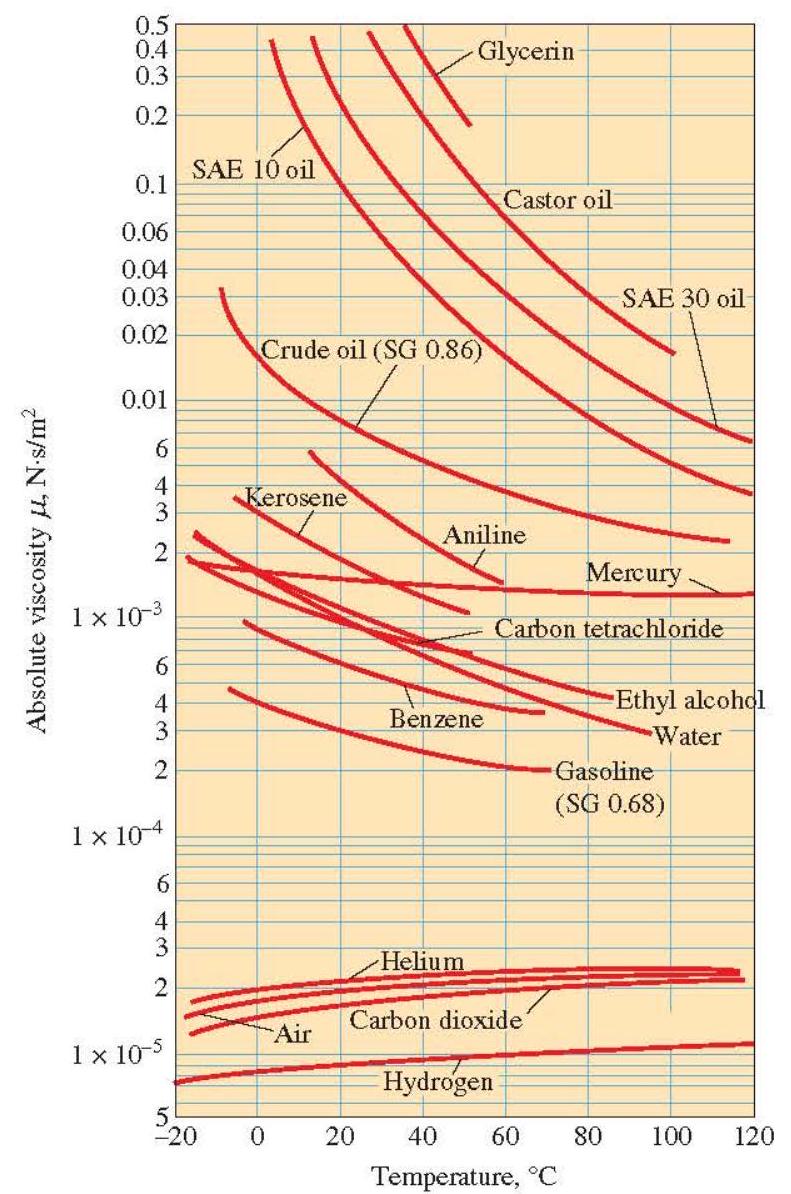
Figure 2-27 The variation of dynamic (absolute) viscosity of common fluids with temperature at (1 \mathrm{~atm}\left(1 \mathrm{~N} \cdot \mathrm{~s} / \mathrm{m}^{2}=1 \mathrm{~kg} / \mathrm{m} \cdot \mathrm{s}=\right.) (\left.0.020886 \mathrm{lbf} \cdot \mathrm{s} / \mathrm{ft}^{2}\right)() White, 2011).
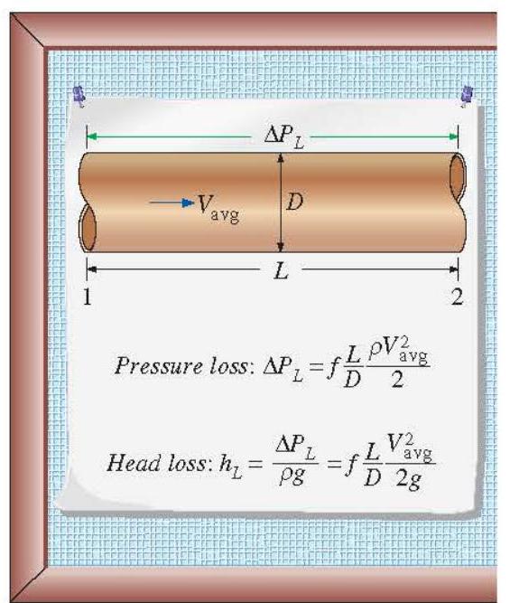
Figure 2-28 The relation for pressure loss (and head loss) is one of the most general relations in fluid mechanics, and it is valid for laminar or turbulent flows, circular or noncircular pipes, and pipes with smooth or rough surfaces.
For fully developed laminar flow in a round pipe, the friction factor is (f=64 / \mathrm{Re}), where (\operatorname{Re}) is Reynolds number (\mathrm{Re}=V D / v). Here, (v) is the kinematic viscosity. Note that the flow is laminar for Reynolds numbers smaller than 2300 and turbulent for Reynolds numbers greater than 4000 .
The head loss represents the additional height that the fluid needs to be raised by a pump in order to overcome the frictional losses in the pipe. The head loss is caused by viscosity, and it is directly related to the wall shear stress.
The pressure drop and the volume flow rate for laminar flow in a horizontal pipe are
[
\begin{gathered}
\Delta P=\frac{32 \mu L V{\mathrm{avg}}}{D^{2}} \
\dot{V}=V{\mathrm{avg}} A_{c}=\frac{\Delta P \pi D^{4}}{128 \mu L}
\end{gathered}
]
This equation is known as Poiseuille's law, and this flow is called Hagen-Poiseuille flow in honor of the works of G. Hagen (1797-1884) and J. Poiseuille (1799-1869) on the subject. Note that for a specified flow rate, the pressure drop and thus the required pumping power is proportional to the length of the pipe and the viscosity of the fluid, but it is inversely proportional to the fourth power of the radius (or diameter) of the pipe. Therefore, the pumping power requirement for a laminar-flow piping system can be reduced by a factor of 16 by doubling the pipe diameter (Fig. 2-29). Of course, the benefits of the reduction in the energy costs must be weighed against the increased cost of construction due to using a larger-diameter pipe.
For noncircular pipes, the diameter in the previous relations is replaced by the hydraulic diameter defined as (D{h}=4 A{c} / p), where (A_{c}) is the cross-sectional area of the pipe and (p) is its wetted perimeter.
In fully developed turbulent flow, the friction factor depends on the Reynolds number and the relative roughness (\varepsilon / D). The friction factor in turbulent flow is given by the Colebrook equation, expressed as
[
\frac{1}{\sqrt{f}}=-2.0 \log \left(\frac{\varepsilon / D}{3.7}+\frac{2.51}{\operatorname{Re} \sqrt{f}}\right)
]
The plot of this formula is known as the Moody chart.
We routinely use the Colebrook equation to calculate the friction factor (f) for fully developed turbulent pipe flow. Indeed, the Moody chart is created using the Colebrook equation. However, in addition to being implicit, the Colebrook equation is valid only for turbulent pipe flow (when the flow is laminar, (f=64 / \mathrm{Re}) ). Thus we need to verify that the
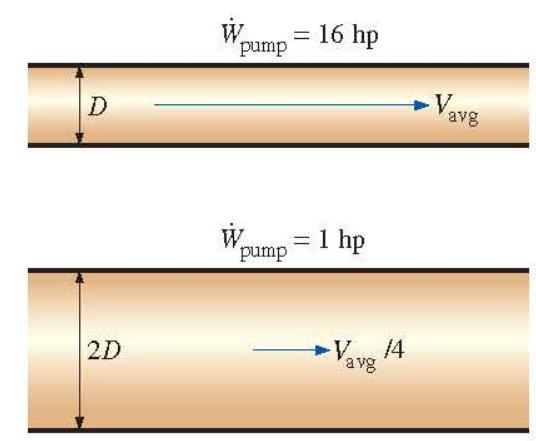
Figure 2-29 The pumping power requirement for a laminar-flow piping system can be reduced by a factor of 16 by doubling the pipe diameter.
Reynolds number is in the turbulent range. An equation was generated by Churchill (1977) that is not only explicit, but is also useful for any Re and any roughness, even for laminar flow, and even in the fuzzy transitional region between laminar and turbulent flow. The Churchill equation is
[
f=8\left[\left(\frac{8}{\mathrm{Re}}\right)^{12}+(A+B)^{-1.5}\right]^{\frac{1}{12}}
]
where
[
A=\left{-2.457 \cdot \ln \left[\left(\frac{7}{\mathrm{Re}}\right)^{0.9}+0.27 \frac{\varepsilon}{D}\right]\right}^{16}
]
The difference between the Colebrook and Churchill equations is less than 1 percent. Because it is explicit and valid over the entire range of Reynolds numbers and roughnesses, it is recommended that the Churchill equation be used for determination of friction factor (f).
Commercially available pipes differ from those used in the experiments in that the roughness of pipes in the market is not uniform and it is difficult to give a precise description of it. Equivalent roughness values for some commercial pipes are given in Table 2-6 as well as on the Moody chart. But it should be kept in mind that these values are for new pipes, and the relative roughness of pipes may increase with use as a result of corrosion, scale buildup, and precipitation. As a result, the friction factor may increase by a factor of 5 to 10 . Actual operating conditions must be considered in the design of piping systems.
Once the pressure loss (or head loss) is known, the required pumping power to overcome the pressure loss is determined from
[
\dot{W}{\text {pump }, L}=\dot{V} \Delta P{L}=\dot{V} \rho g h{L}=\dot{m} g h{L}
]
where (\dot{V}) is the volume flow rate and (\dot{m}) is the mass flow rate.
TABLE 2-6 Equivalent Roughness Values for New Commercial Pipes
\begin{tabular}{|c|c|c|}
\hline \multirow[b]{2}{}{ Material } & \multicolumn{2}{|l|}{ Roughness, (\varepsilon)} \
\hline & ft & mm \
\hline Glass, plastic & \multicolumn{2}{|l|}{0 (smooth) } \
\hline Concrete & (0.003-0.03) & (0.9-9) \
\hline Wood stave & 0.0016 & 0.5 \
\hline Rubber, smoothed & 0.000033 & 0.01 \
\hline Copper or brass tubing & 0.000005 & 0.0015 \
\hline Cast iron & 0.00085 & 0.26 \
\hline Galvanized iron & 0.0005 & 0.15 \
\hline Wrought iron & 0.00015 & 0.046 \
\hline Stainless steel & 0.000007 & 0.002 \
\hline Commercial steel & 0.00015 & 0.045 \
\hline
\end{tabular}
\footnotetext{
*The uncertainty in these values can be as much as (\pm 60) percent.
}
EXAMPLE 2-4 Pressure Drop and Pumping Power
Requirement for Water
Flow in a Pipe
\section*{Requirement for Water
Flow in a Pipe}
Water at (15^{\circ} \mathrm{C}\left(\rho=999.1 \mathrm{~kg} / \mathrm{m}^{3}\right.) and (\left.\mu=1.138 \times 10^{-3} \mathrm{~kg} / \mathrm{m} \cdot \mathrm{s}\right)) is flowing steadily in a (30-\mathrm{m})-long and (5-\mathrm{cm})-internal diameter horizontal pipe made of stainless steel at a rate of (9 \mathrm{~L} / \mathrm{s}) (Fig. 2-30). Determine the pressure drop, the head loss, and the pumping power requirement to overcome this pressure drop.
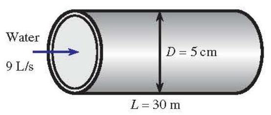
Figure 2-30 Schematic for Example 2-4.
SOLUTION The density and dynamic viscosity of water are given to be (\rho=999.1 \mathrm{~kg} / \mathrm{m}^{3}) and (\mu=1.138 \times 10^{-3} \mathrm{~kg} / \mathrm{m} \cdot \mathrm{s}), respectively. The roughness of stainless steel is 0.002 mm (Table 2-6). First we calculate the average velocity and the Reynolds number to determine the flow regime:
[
\begin{aligned}
V & =\frac{\dot{V}}{A_{c}}=\frac{\dot{V}}{\pi D^{2} / 4}=\frac{0.009 \mathrm{~m}^{3} / \mathrm{s}}{\pi(0.05 \mathrm{~m})^{2} / 4}=4.584 \mathrm{~m} / \mathrm{s} \
\operatorname{Re} & =\frac{\rho V D}{\mu}=\frac{\left(999.1 \mathrm{~kg} / \mathrm{m}^{3}\right)(4.584 \mathrm{~m} / \mathrm{s})(0.05 \mathrm{~m})}{1.138 \times 10^{-3} \mathrm{~kg} / \mathrm{m} \cdot \mathrm{~s}}=2.012 \times 10^{5}
\end{aligned}
]
which is greater than 4000 . Therefore, the flow is turbulent. The relative roughness of the pipe is
[
\varepsilon / D=\frac{2 \times 10^{-6} \mathrm{~m}}{0.05 \mathrm{~m}}=4 \times 10^{-5}
]
The friction factor can be determined from the Moody chart, but to avoid the reading error, we determine it from the Colebrook equation using an equation solver (or an iterative scheme),
[
\frac{1}{\sqrt{f}}=-2.0 \log \left(\frac{\varepsilon / D}{3.7}+\frac{2.51}{\operatorname{Re} \sqrt{f}}\right) \rightarrow \frac{1}{\sqrt{f}}=-2.0 \log \left(\frac{4 \times 10^{-5}}{3.7}+\frac{2.51}{2.012 \times 10^{5} \sqrt{f}}\right)
]
It gives (f=0.01594). Then the pressure drop, head loss, and the required power input become
[
\begin{aligned}
\Delta P & =\Delta P{L}=f \frac{L}{D} \frac{\rho V^{2}}{2} \
& =0.01594 \frac{30 \mathrm{~m}}{0.05 \mathrm{~m}} \frac{\left(999.1 \mathrm{~kg} / \mathrm{m}^{3}\right)(4.584 \mathrm{~m} / \mathrm{s})^{2}}{2}\left(\frac{1 \mathrm{kN}}{1000 \mathrm{~kg} \cdot \mathrm{~m} / \mathrm{s}}\right)\left(\frac{1 \mathrm{kPa}}{1 \mathrm{kN} / \mathrm{m}^{2}}\right) \
& =100.4 \mathrm{kPa} \cong 100 \mathrm{kPa} \
h{L} & =\frac{\Delta P{L}}{\rho g}=f \frac{L}{D} \frac{V^{2}}{2 g}=0.01594 \frac{30 \mathrm{~m}}{0.05 \mathrm{~m}} \frac{(4.584 \mathrm{~m} / \mathrm{s})^{2}}{2\left(9.81 \mathrm{~m} / \mathrm{s}^{2}\right)}=10.2 \mathrm{~m} \
\dot{W}{\text {pump }} & =V \Delta P=\left(0.009 \mathrm{~m}^{3} / \mathrm{s}\right)(100.4 \mathrm{kPa})\left(\frac{1 \mathrm{~kW}}{1 \mathrm{kPa} \cdot \mathrm{~m}^{3} / \mathrm{s}}\right)=0.904 \mathrm{~kW}
\end{aligned}
]
Therefore, useful power input in the amount of 0.904 kW is needed to overcome the frictional losses in the pipe. The power input determined is the mechanical power that needs to be imparted to the fluid. The shaft power will be more than this due to pump inefficiency; the electrical power input will be even more due to motor inefficiency.
In this section, we review basic concepts and principles of thermochemistry, which is thermodynamic study of chemical reactions, particularly combustion reaction.
Fuels and Combustion
Any material that can be burned to release thermal energy is called a fuel. Most familiar fuels consist primarily of hydrogen and carbon. They are called hydrocarbon fuels and are denoted by the general formula (\mathrm{C}{n} \mathrm{H}{m}). Hydrocarbon fuels exist in all phases, some examples being coal, gasoline, and natural gas.
The main constituent of coal is carbon. Coal also contains varying amounts of oxygen, hydrogen, nitrogen, sulfur, moisture, and ash. It is difficult to give an exact mass analysis for coal since its composition varies considerably from one geographical area to the next and even within the same geographical location. Most liquid hydrocarbon fuels are a mixture of numerous hydrocarbons and are obtained from crude oil by distillation. The most volatile hydrocarbons vaporize first, forming what we know as gasoline. The less volatile fuels obtained during distillation are kerosene, diesel fuel, and fuel oil. The composition of a particular fuel depends on the source of the crude oil as well as on the refinery.
Although liquid hydrocarbon fuels are mixtures of many different hydrocarbons, they are usually considered to be a single hydrocarbon for convenience. For example, gasoline is treated as octane, (\mathrm{C}{8} \mathrm{H}{18}), and the diesel fuel as dodecane, (\mathrm{C}{12} \mathrm{H}{26}). Another common liquid hydrocarbon fuel is methyl alcohol, (\mathrm{CH}{3} \mathrm{OH}), which is also called methanol and is used in some gasoline blends. The gaseous hydrocarbon fuel natural gas, which is a mixture of methane and smaller amounts of other gases, is often treated as methane, (\mathrm{CH}{4}), for simplicity.
Natural gas is produced from gas wells or oil wells rich in natural gas. It is composed mainly of methane, but it also contains small amounts of ethane, propane, hydrogen, helium, carbon dioxide, nitrogen, hydrogen sulfate, and water vapor. On vehicles, it is stored either in the gas phase at pressures of 150 to 250 atm as CNG (compressed natural gas), or in the liquid phase at (-162^{\circ} \mathrm{C}) as LNG (liquefied natural gas). Over a million vehicles in the world, mostly buses, run on natural gas. LPG (liquefied petroleum gas) is a by-product of natural gas processing or the crude oil refining. It consists mainly of propane and thus LPG is usually referred to as propane. However, it also contains varying amounts of butane, propylene, and butylene's. Propane is commonly used in fleet vehicles, taxis, school buses, and private cars. Ethanol is obtained from corn, grains, and organic waste. Methanol is produced mostly from natural gas, but it can also be obtained from coal and biomass. Both alcohols are commonly used as additives in oxygenated gasoline and reformulated fuels to reduce air pollution.
Vehicles are a major source of air pollutants such as nitric oxides, carbon monoxide, and hydrocarbons, as well as the greenhouse gas carbon dioxide, and thus there is a growing shift in the transportation industry from the traditional petroleum-based fuels such as gasoline and diesel fuel to the cleaner burning alternative fuels friendlier to the environment such as natural gas, alcohols (ethanol and methanol), LPG, and hydrogen. The use of electric and hybrid cars is also on the rise. Note that the energy contents of alternative fuels per unit volume are lower than that of gasoline or diesel fuel, and thus the driving range of a vehicle on a full tank is lower when running on an alternative fuel.
A chemical reaction during which a fuel is oxidized and a large quantity of energy is released is called combustion. The oxidizer most often used in combustion processes is air, for obvious reasons-it is free and readily available. Pure oxygen (\mathrm{O}{2}) is used as an oxidizer only in some specialized applications, such as cutting and welding, where air cannot be used. Therefore, a few words about the composition of air are in order. On a mole or a
volume basis, dry air is composed of 20.9 percent oxygen, 78.1 percent nitrogen, 0.9 percent argon, and small amounts of carbon dioxide, helium, neon, and hydrogen. In the analysis of combustion processes, the argon in the air is treated as nitrogen, and the gases that exist in trace amounts are disregarded. Then dry air can be approximated as 21 percent oxygen and 79 percent nitrogen by mole numbers. Therefore, each mole of oxygen entering a combustion chamber is accompanied by (0.79 / 0.21=3.76 \mathrm{~mol}) of nitrogen. That is,
[
1 \mathrm{kmol} \mathrm{O}{2}+3.76 \mathrm{kmol} \mathrm{~N}_{2}=4.76 \mathrm{kmol} \text { air }
]
During combustion, nitrogen behaves as an inert gas and does not react with other elements, other than forming a very small amount of nitric oxides. However, even then the presence of nitrogen greatly affects the outcome of a combustion process since nitrogen usually enters a combustion chamber in large quantities at low temperatures and exits at considerably higher temperatures, absorbing a large proportion of the chemical energy released during combustion. Throughout this chapter, nitrogen is assumed to remain perfectly inert. Keep in mind, however, that at very high temperatures, such as those encountered in internal combustion engines, a small fraction of nitrogen reacts with oxygen, forming hazardous gases such as nitric oxide.
Air that enters a combustion chamber normally contains some water vapor (or moisture), which also deserves consideration. For most combustion processes, the moisture in the air and the (\mathrm{H}{2} \mathrm{O}) that forms during combustion can also be treated as an inert gas, like nitrogen. At very high temperatures, however, some water vapor dissociates into (\mathrm{H}{2}) and (\mathrm{O}_{2}) as well as into (\mathrm{H}, \mathrm{O}), and OH . When the combustion gases are cooled below the dew-point temperature of the water vapor, some moisture condenses. It is important to be able to predict the dewpoint temperature since the water droplets often combine with the sulfur dioxide that may be present in the combustion gases, forming sulfuric acid, which is highly corrosive.
During a combustion process, the components that exist before the reaction are called reactants and the components that exist after the reaction are called products. Consider, for example, the combustion of 1 kmol of carbon with 1 kmol of pure oxygen, forming carbon dioxide,
[
\mathrm{C}+\mathrm{O}{2} \rightarrow \mathrm{CO}{2}
]
Here C and (\mathrm{O}{2}) are the reactants since they exist before combustion, and (\mathrm{CO}{2}) is the product since it exists after combustion. Note that a reactant does not have to react chemically in the combustion chamber. For example, if carbon is burned with air instead of pure oxygen, both sides of the combustion equation will include (\mathrm{N}{2}). That is, the (\mathrm{N}{2}) will appear both as a reactant and as a product.
We should also mention that bringing a fuel into intimate contact with oxygen is not sufficient to start a combustion process. (Thank goodness it is not. Otherwise, the whole world would be on fire now.) The fuel must be brought above its ignition temperature to start the combustion. The minimum ignition temperatures of various substances in atmospheric air are approximately (260^{\circ} \mathrm{C}) for gasoline, (400^{\circ} \mathrm{C}) for carbon, (580^{\circ} \mathrm{C}) for hydrogen, (610^{\circ} \mathrm{C}) for carbon monoxide, and (630^{\circ} \mathrm{C}) for methane. Moreover, the proportions of the fuel and air must be in the proper range for combustion to begin. For example, natural gas does not burn in air in concentrations less than 5 percent or greater than about 15 percent.
As you may recall from your chemistry courses, chemical equations are balanced on the basis of the conservation of mass principle (or the mass balance), which can be stated as follows: The total mass of each element is conserved during a chemical reaction. That is, the total mass of each element on the right-hand side of the reaction equation (the products) must be equal to
the total mass of that element on the left-hand side (the reactants) even though the elements exist in different chemical compounds in the reactants and products. Also, the total number of atoms of each element is conserved during a chemical reaction since the total number of atoms is equal to the total mass of the element divided by its atomic mass.
For example, both sides of Eq. (2-32) contain 12 kg of carbon and 32 kg of oxygen, even though the carbon and the oxygen exist as elements in the reactants and as a compound in the product. Also, the total mass of reactants is equal to the total mass of products, each being 44 kg . (It is common practice to round the molar masses to the nearest integer if great accuracy is not required.) However, notice that the total mole number of the reactants ( 2 kmol ) is not equal to the total mole number of the products ( 1 kmol ). That is, the total number of moles is not conserved during a chemical reaction.
A frequently used quantity in the analysis of combustion processes to quantify the amounts of fuel and air is the air-fuel ratio AF. It is usually expressed on a mass basis and is defined as the ratio of the mass of air to the mass offuel for a combustion process (Fig. 2-31). That is,
[
\mathrm{AF}=\frac{m{\mathrm{air}}}{m{\text {fuel }}}
]
The mass (m) of a substance is related to the number of moles (N) through the relation (m=N M), where (M) is the molar mass.
The air-fuel ratio can also be expressed on a mole basis as the ratio of the mole numbers of air to the mole numbers of fuel. But we will use the former definition. The reciprocal of air-fuel ratio is called the fuel-air ratio.
Theoretical and Actual Combustion Processes
It is often instructive to study the combustion of a fuel by assuming that the combustion is complete. A combustion process is complete if all the carbon in the fuel burns to (\mathrm{CO}{2}), all the hydrogen burns to (\mathrm{H}{2} \mathrm{O}), and all the sulfur (if any) burns to (\mathrm{SO}{2}). That is, all the combustible components of a fuel are burned to completion during a complete combustion process. Conversely, the combustion process is incomplete if the combustion products contain any unburned fuel or components such as (\mathrm{C}, \mathrm{H}{2}, \mathrm{CO}), or OH .
Insufficient oxygen is an obvious reason for incomplete combustion, but it is not the only one. Incomplete combustion occurs even when more oxygen is present in the combustion chamber than is needed for complete combustion. This may be attributed to insufficient mixing in the combustion chamber during the limited time that the fuel and the oxygen are in contact. Another cause of incomplete combustion is dissociation, which becomes important at high temperatures.
Oxygen has a much greater tendency to combine with hydrogen than it does with carbon. Therefore, the hydrogen in the fuel normally burns to completion, forming (\mathrm{H}_{2} \mathrm{O}), even when there is less oxygen than needed for complete combustion. Some of the carbon, however, ends up as CO or just as plain C particles (soot) in the products.
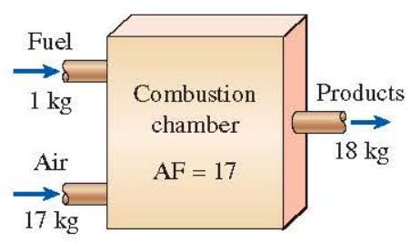
Figure 2-31 The air-fuel ratio (AF) represents the amount of air used per unit mass of fuel during a combustion process.
The minimum amount of air needed for the complete combustion of a fuel is called the stoichiometric or theoretical air. Thus, when a fuel is completely burned with theoretical air, no uncombined oxygen is present in the product gases. The theoretical air is also referred to as the chemically correct amount of air, or 100 percent theoretical air. A combustion process with less than the theoretical air is bound to be incomplete. The ideal combustion process during which a fuel is burned completely with theoretical air is called the stoichiometric or theoretical combustion of that fuel. For example, the theoretical combustion of methane is
[
\mathrm{CH}{4}+2\left(\mathrm{O}{2}+3.76 \mathrm{~N}{2}\right) \rightarrow \mathrm{CO}{2}+2 \mathrm{H}{2} \mathrm{O}+7.52 \mathrm{~N}{2}
]
Notice that the products of the theoretical combustion contain no unburned methane and no C, (\mathrm{H}{2}, \mathrm{CO}, \mathrm{OH}), or free (\mathrm{O}{2}).
In actual combustion processes, it is common practice to use more air than the stoichiometric amount to increase the chances of complete combustion or to control the temperature of the combustion chamber. The amount of air in excess of the stoichiometric amount is called excess air. The amount of excess air is usually expressed in terms of the stoichiometric air as percent excess air or percent theoretical air. For example, 50 percent excess air is equivalent to 150 percent theoretical air, and 200 percent excess air is equivalent to 300 percent theoretical air. Of course, the stoichiometric air can be expressed as 0 percent excess air or 100 percent theoretical air. Amounts of air less than the stoichiometric amount are called deficiency of air and are often expressed as percent deficiency of air. For example, 90 percent theoretical air is equivalent to 10 percent deficiency of air. The amount of air used in combustion processes is also expressed in terms of the equivalence ratio, which is the ratio of the actual fuel-air ratio to the stoichiometric fuel-air ratio.
Predicting the composition of the products is relatively easy when the combustion process is assumed to be complete and the exact amounts of the fuel and air used are known. All one needs to do in this case is simply apply the mass balance to each element that appears in the combustion equation, without needing to take any measurements. Things are not so simple, however, when one is dealing with actual combustion processes. For one thing, actual combustion processes are hardly ever complete, even in the presence of excess air. Therefore, it is impossible to predict the composition of the products on the basis of the mass balance alone. Then the only alternative we have is to measure the amount of each component in the products directly.
Enthalpy of Formation and Enthalpy of Combustion
During a chemical reaction, some chemical bonds that bind the atoms into molecules are broken, and new ones are formed. The chemical energy associated with these bonds, in general, is different for the reactants and the products. Therefore, a process that involves chemical reactions involves changes in chemical energies, which must be accounted for in an energy balance. Assuming the atoms of each reactant remain intact (nonnuclear reactions) and disregarding any changes in kinetic and potential energies, the energy change of a system during a chemical reaction is due to a change in state and a change in chemical composition. That is,
[
\Delta E{\text {sys }}=\Delta E{\text {state }}+\Delta E_{\text {chem }}
]
Therefore, when the products formed during a chemical reaction exit the reaction chamber at the inlet state of the reactants, we have (\Delta E_{\text {state }}=0) and the energy change of the system in this case is due to the changes in its chemical composition only.
In thermodynamics we are concerned with the changes in the energy of a system during a process, and not the energy values at the particular states. Therefore, we can choose any state as the reference state and assign a value of zero to the internal energy or enthalpy of a substance at that state. When a process involves no changes in chemical composition, the reference state chosen has no effect on the results. When the process involves chemical reactions, however, the composition of the system at the end of a process is no longer the same as that at the beginning of the process. In this case, it becomes necessary to have a common reference state for all substances. The chosen reference state is (25^{\circ} \mathrm{C}\left(77^{\circ} \mathrm{F}\right)) and 1 atm , which is known as the standard reference state. Property values at the standard reference state are indicated by "o" such as (h^{\circ}) and (u^{\circ}).
When analyzing reacting systems, we must use property values relative to the standard reference state. However, it is not necessary to prepare a new set of property tables for this purpose. We can use the existing tables by subtracting the property values at the standard reference state from the values at the specified state. The ideal-gas enthalpy of (\mathrm{N}{2}) at 500 K relative to the standard reference state, for example, is (\bar{h}{500 \mathrm{~K}}-\bar{h}^{\circ}=14,581-8669=5912 \mathrm{~kJ} / \mathrm{kmol}).
Consider the formation of (\mathrm{CO}{2}) from its elements, carbon and oxygen, during a steadyflow combustion process. Both the carbon and the oxygen enter the combustion chamber at (25^{\circ} \mathrm{C}) and 1 atm . The (\mathrm{CO}{2}) formed during this process also leaves the combustion chamber at (25^{\circ} \mathrm{C}) and 1 atm . The combustion of carbon is an exothermic reaction (a reaction during which chemical energy is released in the form of heat). Therefore, some heat is transferred from the combustion chamber to the surroundings during this process, which is (393,520 \mathrm{~kJ} / \mathrm{kmol}) (\mathrm{CO}_{2}) formed. (When one is dealing with chemical reactions, it is more convenient to work with quantities per unit mole than per unit time, even for steady-flow processes.)
The process described above involves no work interactions. Therefore, from the steadyflow energy balance relation, the heat transfer during this process must be equal to the difference between the enthalpy of the products and the enthalpy of the reactants. That is,
[
Q=H{\text {prod }}-H{\text {react }}=-393,520 \mathrm{~kJ} / \mathrm{kmol}
]
Since both the reactants and the products are at the same state, the enthalpy change during this process is solely due to the changes in the chemical composition of the system. This enthalpy change is different for different reactions, and it is very desirable to have a property to represent the changes in chemical energy during a reaction. This property is the enthalpy of reaction (h_{R}), which is defined as the difference between the enthalpy of the products at a specified state and the enthalpy of the reactants at the same state for a complete reaction.
For combustion processes, the enthalpy of reaction is usually referred to as the enthalpy of combustion (h{C}) which represents the amount of heat released during a steady-flow combustion process when 1 kmol (or 1 kg ) of fuel is burned completely at a specified temperature and pressure (Fig. 2-32). It is expressed as
[
h{R}=h{C}=H{\text {prod }}-H_{\text {react }}
]
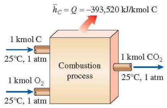
Figure 2-32 The enthalpy of combustion represents the amount of energy released as a fuel is burned during a steady-flow process at a specified state.
which is (-393,520 \mathrm{~kJ} / \mathrm{kmol}) for carbon at the standard reference state. The enthalpy of combustion of a particular fuel is different at different temperatures and pressures.
The enthalpy of combustion is obviously a very useful property for analyzing the combustion processes of fuels. However, there are so many different fuels and fuel mixtures that it is not practical to list (h{C}) values for all possible cases. Besides, the enthalpy of combustion is not of much use when the combustion is incomplete. Therefore, a more practical approach would be to have a more fundamental property to represent the chemical energy of an element or a compound at some reference state. This property is the enthalpy of formation (\bar{h}{f}^{\circ}), which can be viewed as the enthalpy of a substance at a specified state due to its chemical composition.
To establish a starting point, we assign the enthalpy of formation of all stable elements (such as (\mathrm{O}{2}, \mathrm{~N}{2}, \mathrm{H}{2}), and C ) a value of zero at the standard reference state of (25^{\circ} \mathrm{C}) and 1 atm . That is, (\bar{h}{f}^{\circ}=0) for all stable elements. (This is no different from assigning the internal energy of saturated liquid water a value of zero at (0.01^{\circ} \mathrm{C}).) Perhaps we should clarify what we mean by stable. The stable form of an element is simply the chemically stable form of that element at (25^{\circ} \mathrm{C}) and 1 atm . Nitrogen, for example, exists in diatomic form (\left(\mathrm{N}{2}\right)) at (25^{\circ} \mathrm{C}) and 1 atm . Therefore, the stable form of nitrogen at the standard reference state is diatomic nitrogen (\mathrm{N}{2}), not monatomic nitrogen N . If an element exists in more than one stable form at (25^{\circ} \mathrm{C}) and 1 atm , one of the forms should be specified as the stable form. For carbon, for example, the stable form is assumed to be graphite, not diamond.
Now reconsider the formation of (\mathrm{CO}{2}) (a compound) from its elements C and (\mathrm{O}{2}) at (25^{\circ} \mathrm{C}) and 1 atm during a steady-flow process. The enthalpy change during this process was determined to be (-393,520 \mathrm{~kJ} / \mathrm{kmol}). However, (H{\text {react }}=0) since both reactants are elements at the standard reference state, and the products consist of 1 kmol of (\mathrm{CO}{2}) at the same state. Therefore, the enthalpy of formation of (\mathrm{CO}_{2}) at the standard reference state is (-393,520 \mathrm{~kJ} / \mathrm{kmol}).
The negative sign is due to the fact that the enthalpy of 1 kmol of (\mathrm{CO}{2}) at (25^{\circ} \mathrm{C}) and 1 atm is (393,520 \mathrm{~kJ}) less than the enthalpy of 1 kmol of C and 1 kmol of (\mathrm{O}{2}) at the same state. In other words, (393,520 \mathrm{~kJ}) of chemical energy is released (leaving the system as heat) when C and (\mathrm{O}{2}) combine to form 1 kmol of (\mathrm{CO}{2}). Therefore, a negative enthalpy of formation for a compound indicates that heat is released during the formation of that compound from its stable elements. A positive value indicates heat is absorbed.
You will notice that two (\bar{h}{f}^{\circ}) values are given for (\mathrm{H}{2} \mathrm{O}) in Table A-6 in the appendix, one for liquid water and the other for water vapor. This is because both phases of (\mathrm{H}{2} \mathrm{O}) are encountered at (25^{\circ} \mathrm{C}), and the effect of pressure on the enthalpy of formation is small. (Note that under equilibrium conditions, water exists only as a liquid at (25^{\circ} \mathrm{C}) and 1 atm .) The difference between the two enthalpies of formation is equal to the (h{f 8}) of water at (25^{\circ} \mathrm{C}), which is (2441.7 \mathrm{~kJ} / \mathrm{kg}) or (44,000 \mathrm{~kJ} / \mathrm{kmol}).
Another term commonly used in conjunction with the combustion of fuels is the heating value of the fuel, which is defined as the amount of heat released when a fuel is burned completely in a steady-flow process and the products are returned to the state of the reactants. In other words, the heating value of a fuel is equal to the absolute value of the enthalpy of combustion of the fuel. That is,
[
\text { Heating value }=\mid h \mathrm{~d} \quad(\mathrm{~kJ} / \mathrm{kg} \text { fuel })
]
The heating value depends on the phase of the (\mathrm{H}{2} \mathrm{O}) in the products. The heating value is called the higher heating value (HHV) when the (\mathrm{H}{2} \mathrm{O}) in the products is in the liquid form, and it is called the lower heating value (LHV) when the (\mathrm{H}{2} \mathrm{O}) in the products is in the vapor form (Fig. 2-33). The two heating values are related by
[
\mathrm{HHV}=\mathrm{LHV}+\left(\mathrm{mh}{\mathrm{f}{g}}\right){\mathrm{H}_{2} \mathrm{O}} \quad(\mathrm{~kJ} / \mathrm{kg} \text { fuel })
]
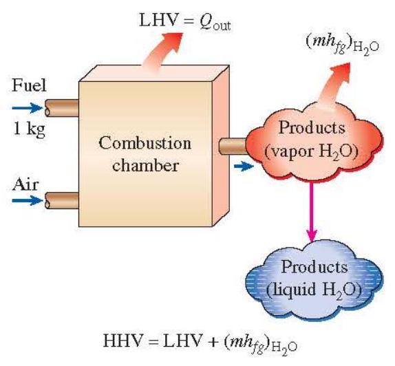
Figure 2-33 The higher heating value of a fuel is equal to the sum of the lower heating value of the fuel and the latent heat of vaporization of the (\mathrm{H}{2} \mathrm{O}) in the products.
where (m) is the mass of (\mathrm{H}{2} \mathrm{O}) in the products per unit mass of fuel and (h_{f g}) is the enthalpy of vaporization of water at the specified temperature. Higher and lower heating values of common fuels are given in Table A-7 in the appendix. The heating value or enthalpy of combustion of a fuel can be determined from a knowledge of the enthalpy of formation for the compounds involved.
When the exact composition of the fuel is known, the enthalpy of combustion of that fuel can be determined using enthalpy of formation data. However, for fuels that exhibit considerable variations in composition depending on the source, such as coal, natural gas, and fuel oil, it is more practical to determine their enthalpy of combustion experimentally by burning them directly in a bomb calorimeter at constant volume or in a steady-flow device.
First-Law Analysis of Reacting Systems
The energy balance (or the first-law) relations developed earlier are applicable to both reacting and nonreacting systems. However, chemically reacting systems involve changes in their chemical energy, and thus itis more convenient to rewrite the energy balance relations so that the changes in chemical energies are explicitly expressed. We do this for steady-flow systems.
Before writing the energy balance relation, we need to express the enthalpy of a component in a form suitable for use for reacting systems. That is, we need to express the enthalpy such that it is relative to the standard reference state and the chemical energy term appears explicitly. When expressed properly, the enthalpy term should reduce to the enthalpy of formation at the standard reference state. With this in mind, we express the enthalpy of a component on a unit mole basis as
[
\text { Enthalpy }=\bar{h}{f}^{\circ}+\left(\bar{h}-\bar{h}^{\circ}\right) \quad(\mathrm{kJ} / \mathrm{kmol})
]
where the term in the parentheses represents the sensible enthalpy relative to the standard reference state, which is the difference between (the sensible enthalpy at the specified state) and (the sensible enthalpy at the standard reference state of (25^{\circ} \mathrm{C}) and 1 atm ). This definition enables us to use enthalpy values from tables regardless of the reference state used in their construction. The sensible enthalpy can be approximated as (\left(\bar{h}-\bar{h}^{\circ}\right) \cong \bar{c}{p} \Delta T), where (\bar{c}_{p}) is the specific heat on a molar basis and (\Delta T) is the difference in product temperature and reference state temperature.
When the changes in kinetic and potential energies are negligible, the steady-flow energy balance relation (\dot{E}{\text {in }}=\dot{E}{\text {out }}) can be expressed for a chemically reacting steady-flow system more explicitly as
[
\dot{Q}{\text {in }}+\dot{W}{\text {in }}+\sum \dot{n}{r}\left(\bar{h}{f}^{\circ}+\bar{h}-\bar{h}^{\circ}\right){r}=\dot{Q}{\text {out }}+\dot{W}{\text {out }}+\sum \dot{n}{p}\left(\bar{h}{f}^{\circ}+\bar{h}-\bar{h}^{\circ}\right){p}
]
where (\dot{n}{p}) and (\dot{n}{r}) represent the molal flow rates of the product (p) and the reactant (r), respectively.
In combustion analysis, it is more convenient to work with quantities expressed per mole of fuel. Such a relation is obtained by dividing each term of the equation above by the molal flow rate of the fuel, yielding
[
Q{\text {in }}+W{\text {in }}+\sum N{r}\left(\bar{h}{f}^{\circ}+\bar{h}-\bar{h}^{\circ}\right){r}=Q{\text {out }}+W{\text {out }}+\sum N{p}\left(\bar{h}{f}^{\circ}+\bar{h}-\bar{h}^{\circ}\right){p}
]
where (N{r}) and (N{p}) represent the number of moles of the reactant (r) and the product (p), respectively, per mole of fuel. Note that (N{r}=1) for the fuel, and the other (N{r}) and (N_{p}) values can be picked directly from the balanced combustion equation. The energy balance relations above are sometimes written without the work term since most steady-flow combustion processes do not involve any work interactions.
A combustion chamber normally involves heat output but no heat input. Then the energy balance for a typical steady-flow combustion process becomes
[
Q{\text {out }}=\sum N{r}\left(\bar{h}{f}^{\circ}+\bar{h}-\bar{h}^{\circ}\right){\tau}-\sum N{p}\left(\bar{h}{f}^{\circ}+\bar{h}-\bar{h}^{\circ}\right)_{p}
]
It expresses that the heat output during a combustion process is simply the difference between the energy of the reactants entering and the energy of the products leaving the combustion chamber.
EXAMPLE 2-5 A gaseous fuel mixture that is 40 percent propane (\left(\mathrm{C}{3} \mathrm{H}{8}\right)) and 60 percent methane (\left(\mathrm{CH}{4}\right)) by volume is Analysis of a Combustion burned at a rate of (3.75 \mathrm{~kg} / \mathrm{h}) with 50 percent excess dry air (Fig. 2-34) in the combustion chamber of Process an equipment producing heat (such as a boiler). Both the fuel and air enter the combustion chamber at (25^{\circ} \mathrm{C}) and 100 kPa and undergo a complete combustion process. Combustion products leave the combustion chamber at (125^{\circ} \mathrm{C}). Determine (a) the balanced combustion equation, (b) the air-fuel ratio, (c) the dew-point temperature of product gases, ((d)) the mass of (\mathrm{CO}{2}) formed per unit mass of the fuel, and ((e)) the rate of heat produced in the equipment. Enthalpy of formation, molar mass, and specific heat data for the species are given in the following table.
\begin{tabular}{lccc}
\hline & (\bar{h}{\rho}^{\rho}, \mathrm{k} J / \mathrm{kmol}) & (M, \mathrm{~kg} / \mathrm{kmol}) & (\bar{c}{p}, \mathrm{~kJ} / \mathrm{kmol} \cdot \mathrm{K}) \
\hline (\mathrm{C}{3} \mathrm{H}{8}(g)) & (-103,850) & 44 & \
(\mathrm{CH}{4}(\mathrm{~g})) & (-74,850) & 16 & \
(\mathrm{CO}{2}) & (-393,520) & 44 & 41.16 \
(\mathrm{CO}{2}) & (-110,530) & 28 & 29.21 \
(\mathrm{H}{2} \mathrm{O}(g)) & (-241,820) & 18 & 34.28 \
(\mathrm{H}{2} \mathrm{O}(l)) & (-285,830) & 18 & 75.24 \
(\mathrm{O}{2}) & & 32 & 30.14 \
(\mathrm{~N}_{2}) & & 28 & 29.27 \
\hline
\end{tabular}
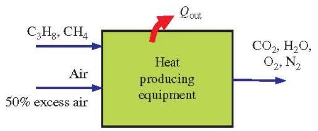
Figure 2-34 Schematic for Example 2-5.
SOLUTION (a) The process is shown in Fig. 2-34. The balanced reaction equation with the stoichiometric air is
[
0.4 \mathrm{C}{3} \mathrm{H}{8}+0.6 \mathrm{CH}{4}+a{\mathrm{th}}\left[\mathrm{O}{2}+3.76 \mathrm{~N}{2}\right] \rightarrow 1.8 \mathrm{CO}{2}+2.8 \mathrm{H}{2} \mathrm{O}+a{\mathrm{th}} \times 3.76 \mathrm{~N}{2}
]
The stoichiometric coefficient (a{\mathrm{th}}) is determined from an (\mathrm{O}{2}) balance:
[
a_{\mathrm{th}}=1.8+1.4=3.2
]
Substituting,
[
0.4 \mathrm{C}{3} \mathrm{H}{8}+0.6 \mathrm{CH}{4}+3.2\left[\mathrm{O}{2}+3.76 \mathrm{~N}{2}\right] \rightarrow 1.8 \mathrm{CO}{2}+2.8 \mathrm{H}{2} \mathrm{O}+12.032 \mathrm{~N}{2}
]
There will be extra (\mathrm{O}{2}) formed in the products when the reaction takes place with 50 percent excess air. Also, more (\mathrm{N}{2}) will be formed:
[
0.4 \mathrm{C}{3} \mathrm{H}{8}+0.6 \mathrm{CH}{4}+1.5 \times 3.2\left[\mathrm{O}{2}+3.76 \mathrm{~N}{2}\right] \rightarrow 1.8 \mathrm{CO}{2}+2.8 \mathrm{H}{2} \mathrm{O}+1.5 \times 12.032 \mathrm{~N}{2}+0.5 \times 3.2 \mathrm{O}_{2}
]
That is,
[
0.4 \mathrm{C}{3} \mathrm{H}{8}+0.6 \mathrm{CH}{4}+4.8\left[\mathrm{O}{2}+3.76 \mathrm{~N}{2}\right] \rightarrow 1.8 \mathrm{CO}{2}+2.8 \mathrm{H}{2} \mathrm{O}+18.05 \mathrm{~N}{2}+1.6 \mathrm{O}{2}
]
(b) The air-fuel ratio is
[
\mathrm{AF}=\frac{m{\text {air }}}{m{\text {fuel }}}=\frac{(4.8 \times 4.76 \times 29) \mathrm{kg}}{(0.4 \times 44+0.6 \times 16) \mathrm{kg}}=24.36 \mathrm{~kg} \text { air } / \mathrm{kg} \text { fuel }
]
(c) The partial pressure of water vapor is determined by multiplying the molar fraction of water in the products (\left(y{\mathrm{H}{2} \mathrm{O}}=N{\mathrm{H}{2} \mathrm{O}} / N{\text {total }}\right)) by the total pressure of the product gases:
[
P{v}=y{\mathrm{H}{2} \mathrm{O}} P{\text {total }}=\frac{N{\mathrm{H}{2} \mathrm{O}}}{N{\text {total }}} P{\text {total }}=\frac{2.8}{1.8+2.8+18.05+1.6}(100 \mathrm{kPa})=\frac{2.8 \mathrm{kmol}}{24.25 \mathrm{kmol}}(100 \mathrm{kPa})=11.55 \mathrm{kPa}
]
The dew point temperature of the product gases is the saturation temperature of water at this pressure:
[
T{d p}=T{\text {sat@ 11.55 kPa }}=48.7^{\circ} \mathrm{C} \quad \text { (Table A-4) }
]
Since the temperature of the product gases is at (398 \mathrm{~K}\left(125^{\circ} \mathrm{C}\right)), which is greater than the dew point temperature, there will be no condensation of water vapor in the product gases. If the temperature of exhaust gases drop below this temperature as it flows in piping and chimney, water vapor will start condensing.
(d) The mass of (\mathrm{CO}{2}) formed per unit mass of the fuel is
[
\begin{aligned}
\frac{m{\mathrm{CO}{2}}}{m{\mathrm{fuel}}} & =\frac{N{\mathrm{CO}{2}} M{\mathrm{CO}{2}}}{\left(N{\mathrm{C}{3} \mathrm{H}{8}} M{\mathrm{C}{3} \mathrm{H}{8}}\right)+\left(N{\mathrm{CH}{4}} M{\mathrm{CH}{4}}\right)} \
& =\frac{(1.8 \mathrm{kmol})(44 \mathrm{~kg} / \mathrm{kmol})}{(0.4 \mathrm{kmol})(44 \mathrm{~kg} / \mathrm{kmol})+(0.6 \mathrm{kmol})(16 \mathrm{~kg} / \mathrm{kmol})} \
& =\frac{79.2 \mathrm{~kg}}{27.2 \mathrm{~kg}}=\mathbf{2 . 9 2} \mathrm{kg} \mathrm{CO}_{2} / \mathbf{k g} \text { fuel }
\end{aligned}
]
When 1 kg of this fuel mixture is burned, 2.92 kg of (\mathrm{CO}{2}) gas (a major greenhouse gas causing global warming) is formed in the product gases. Note that the amount of (\mathrm{CO}{2}) production is the same when the combustion is with theoretical air or with excess air as long as the combustion is complete. That is, using excess air does not affect the amount of (\mathrm{CO}{2}) production.
(e) The heat transfer for this combustion process is determined from the energy balance (E{\text {in }}-E{\text {out }}=) (\Delta E{\text {system }}) applied on the combustion chamber with (W=0). It reduces to
[
-Q{\text {out }}=\sum N{p}\left(\bar{h}{f}^{\circ}+\bar{h}-\bar{h}^{\circ}\right){p}-\sum N{r}\left(\bar{h}{f}^{\circ}+\bar{h}-\bar{h}^{\circ}\right)_{r}
]
The products are at (125^{\circ} \mathrm{C}), and the enthalpy of products can be expressed as
[
\bar{h}-\bar{h}^{\circ}=\bar{c}{p} \Delta T
]
where (\Delta T=125-25=100^{\circ} \mathrm{C}=100 \mathrm{~K}). Then, using the values given in the table,
[
\begin{aligned}
-Q{\text {out }}= & (1.8)(-393,520+41.16 \times 100)+(2.8)(-241,820+34.28 \times 100) \
& +(18.05)(0+29.27 \times 100)+(1.6)(0+30.14 \times 100)-(0.4)(-103,850)-(0.6)(-74,850) \
= & -1,224,320 \mathrm{~kJ} / \mathrm{kmol} \text { fuel }
\end{aligned}
]
or (Q{\text {out }}=1,224,320 \mathrm{~kJ} / \mathrm{kmol}) fuel
The rate of heat output from the equipment for a fuel consumption rate of (3.75 \mathrm{~kg} / \mathrm{h}) is
[
\dot{Q}{\text {out }}=\tilde{m}{\text {fuel }} \frac{Q{\text {out }}}{M_{\text {fuel }}}=(3.75 \mathrm{~kg} \text { fuel } / \mathrm{h}) \frac{1,224,320 \mathrm{~kJ} / \mathrm{kmol} \text { fuel }}{(0.4 \times 44+0.6 \times 16) \mathrm{kg} / \mathrm{kmol}}=168,794 \mathrm{~kJ} / \mathrm{h}=46.9 \mathrm{~kW}
]
That is, this equipment supplies heat at a rate of 46.9 kW . If this is a boiler generating hot water, the value of 46.9 kW represents the rate of heat transferred to the water in the boiler.
6 HEAT ENGINES AND POWER PLANTS
Work can easily be converted to other forms of energy, but converting other forms of energy to work is not that easy. Work can be converted to heat directly and completely, but converting heat to work requires the use of some special devices. These devices are called heat engines. Heat engines differ considerably from one another, but all can be characterized by the following (Fig. 2-35):
- They receive heat from a high-temperature source (solar energy, oil furnace, nuclear reactor, etc.).
- They convert part of this heat to work (usually in the form of a rotating shaft).
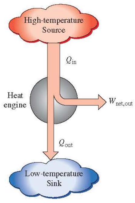
Figure 2-35 Part of the heat received by a heat engine is converted to work, while the rest is rejected to a sink.
- They reject the remaining waste heat to a low-temperature sink (the atmosphere, rivers, etc.).
- They operate on a cycle.
Heat engines and other cyclic devices usually involve a fluid to and from which heat is transferred while undergoing a cycle. This fluid is called the working fluid.
The term heat engine is often used in a broader sense to include work-producing devices that do not operate in a thermodynamic cycle. Engines that involve internal combustion such as gas turbines and car engines fall into this category. These devices operate in a mechanical cycle but not in a thermodynamic cycle since the working fluid (the combustion gases) does not undergo a complete cycle. Instead of being cooled to the initial temperature, the exhaust gases are purged and replaced by fresh air-and-fuel mixture at the end of the cycle.
The work-producing device that best fits into the definition of a heat engine is the steam power plant, which is an external-combustion engine. That is, combustion takes place outside the engine, and the thermal energy released during this process is transferred to the steam as heat. The schematic of a basic steam power plant is shown in Fig. 2-36. The various quantities shown on this figure are as follows:
(Q{\text {in }}=) amount of heat supplied to steam in boiler from a high-temperature source (furnace)
(Q{\text {out }}=) amount of heat rejected from steam in condenser to a low-temperature sink (the atmosphere, a river, etc.)
(W{\text {out }}=) amount of work delivered by steam as it expands in turbine
(W{\text {in }}=) amount of work required to compress water to boiler pressure
Notice that the directions of the heat and work interactions are indicated by the subscripts in and out. Therefore, all four of the described quantities are always positive.
The network output of this power plant is simply the difference between the total work output of the plant and the total work input (Fig. 2-37):
[
W{\text {net,out }}=W{\text {out }}-W_{\text {in }}
]
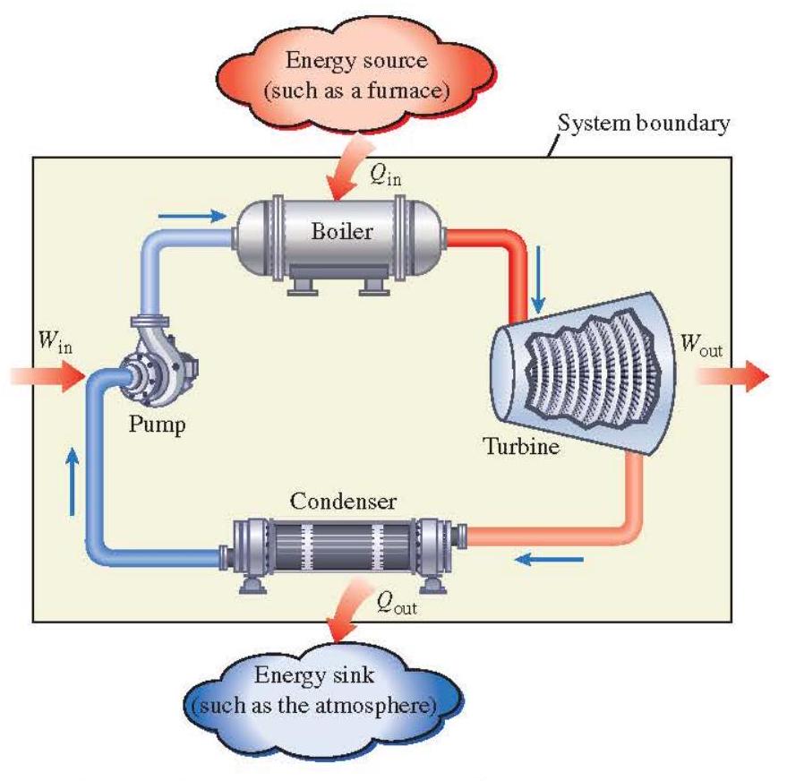
Figure 2-36 Schematic of a steam power plant.
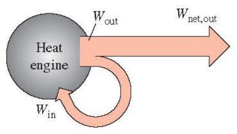
Figure 2-37 A portion of the work output of a heat engine is consumed internally to maintain continuous operation.
The network can also be determined from the heat transfer data alone. The four components of the steam power plant involve mass flow in and out, and therefore should be treated as open systems. These components, together with the connecting pipes, however, always contain the same fluid (not counting the steam that may leak out, of course). No mass enters or leaves this combination system, which is indicated by the shaded area on Fig. 2-36; thus, it can be analyzed as a closed system. Recall that for a closed system undergoing a cycle, the change in internal energy (\Delta U) is zero, and therefore the net work output of the system is also equal to the net heat transfer to the system:
[
W{\text {netout }}=Q{\text {in }}-Q_{\text {out }}
]
Thermal Efficiency
In Eq. (2-42), (Q{\text {out }}) represents the magnitude of the energy wasted in order to complete the cycle. But (Q{\text {out }}) is never zero; thus, the net work output of a heat engine is always less than the amount of heat input. That is, only part of the heat transferred to the heat engine is converted to work. The fraction of the heat input that is converted to net work output is a measure of the performance of a heat engine and is called the thermal efficiency (\eta_{\mathrm{th}}) (Fig. 2-38).
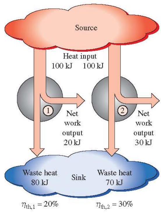
Figure 2-38 Some heat engines perform better than others (convert more of the heat they receive to work).
For heat engines, the desired output is the net work output, and the required input is the amount of heat supplied to the working fluid. Then the thermal efficiency of a heat engine can be expressed as
[
\eta{\text {th }}=\frac{\text { Net work output }}{\text { Total heat input }}=\frac{W{\text {netout }}}{Q_{\text {in }}}
]
Using net power and rate of heat input,
[
\eta{\mathrm{th}}=\frac{\text { Net power output }}{\text { Total rate of heat input }}=\frac{\dot{W}{\text {netout }}}{\dot{Q}_{\text {in }}}
]
It can also be expressed as
[
\eta{\mathrm{th}}=1-\frac{Q{\text {out }}}{Q{\text {in }}}
]
since (W{\text {net, out }}=Q{\text {in }}-Q{\text {out }})
Thermal efficiency is a measure of how efficiently a heat engine converts the heat that it receives to work. Heat engines are built for the purpose of converting heat to work, and engineers are constantly trying to improve the efficiencies of these devices since increased efficiency means less fuel consumption and thus lower fuel bills and less pollution.
The most efficient heat engine cycle is referred to as Carnot cycle, which consists of totally reversible processes. The thermal efficiency of Carnot cycle can be expressed in terms of temperatures as
[
\eta{\text {th, Carnot }}=1-\frac{T{L}}{T{H}}
]
where (T{L}) and (T{H}) are the temperatures of the low-temperature and high-temperature reservoirs (i.e., sink and source temperatures), respectively. Notice that thermal efficiency of Carnot heat engine increases with increasing (T{H}) and decreasing (T_{L}) values. The Carnot cycle is the most efficient heat engine cycle operating between two specified temperature levels.
Overall Plant Efficiency
In electricity generating plants, heat is usually supplied by burning fuels such as coal, oil, and natural gas. For example, in a steam power plant, the chemical energy of fuel is converted to heat in a combustion process. Most of the produced heat is transferred to water to turn it into steam, which runs through the turbine to produce power. The remaining heat is lost to the environment with the exhaust gases of the combustion process.
We may define an overall plant efficiency based on the total energy of the fuel consumed in the plant:
[
\eta{\text {plant }}=\frac{\text { Net work output }}{\text { Total amount of heat input by fuel }}=\frac{W{\text {netoout }}}{m{\text {fuel }} \times H V{\text {fuel }}}
]
where (W{\text {netout }}(\mathrm{kJ})) is the net work output from the plant, (m{\text {fuel }}(\mathrm{kg})) is the amount of fuel consumed and (\mathrm{HV}{\text {fuel }}(\mathrm{kJ} / \mathrm{kg})) is the heating value of the fuel. It may also be expressed on a rate basis as
[
\eta{\text {plant }}=\frac{\text { Net power output }}{\text { Total rate of heat input by fuel }}=\frac{\dot{W}{\text {net,out }}}{\dot{m}{\text {fuel }} \times \mathrm{HV}{\text {fuel }}}
]
where (\dot{W}{\text {net,out }}(\mathrm{kW})) is the net power output from the plant and (\dot{m}_{\text {fuel }}(\mathrm{kg} / \mathrm{s})) is the mass rate of fuel consumed. The overall plant efficiency can be used to express the performance of all power plants which burn a fuel such as steam power plants, gas-turbine power plants, and automobile engines. Note that the thermal efficiency and overall plant efficiency are sometimes used interchangeably.
The overall plant efficiencies of power plants are relatively low. Ordinary spark-ignition automobile engines have an efficiency of about 25 percent. That is, an automobile engine converts about 25 percent of the chemical energy of the gasoline to mechanical work. This number is as high as 40 percent for diesel engines and large gas-turbine plants and as high as 60 percent for large combined gas-steam power plants. Thus, even with the most efficient heat engines available today, almost one-half of the energy supplied ends up in the rivers, lakes, or the atmosphere as waste or useless energy.
EXAMPLE 2-6 A coal-fired power plant generates 1100 MW power with an overall plant efficiency of 44 percent. The Coal Consumption of a plant operates 75 percent of time a year. The coal used in the plant has a heating value of (26,000 \mathrm{~kJ} / \mathrm{kg}). Power Plant Determine the amount of coal consumed in the plant per year.
SOLUTION The plant operates 75 percent of the time. Then, the annual operating hours is
Operating days (=(0.75)(365 \times 24 \mathrm{~h} / \mathrm{yr})=6570 \mathrm{~h} / \mathrm{yr})
The rate of heat input to the plant is determined using plant efficiency as
[
\eta{\text {plant }}=\frac{\dot{W}{\text {electric }}}{\dot{Q}{\text {in }}} \rightarrow \dot{Q}{\text {in }}=\frac{\dot{W}{\text {electric }}}{\eta{\text {plant }}}=\frac{1100 \mathrm{MW}}{0.44}=2500 \mathrm{MW}
]
The amount of heat input to the plant per year is
[
Q{\mathrm{in}}=\dot{Q}{\mathrm{in}} \times \text { Operating days }=(2500 \mathrm{MJ} / \mathrm{s})(6570 \mathrm{~h} / \mathrm{yr})\left(\frac{3600 \mathrm{~s}}{1 \mathrm{~h}}\right)\left(\frac{1000 \mathrm{~kJ}}{1 \mathrm{MJ}}\right)=5.913 \times 10^{13} \mathrm{~kJ} / \mathrm{yr}
]
The corresponding coal consumption of the plant per year is
[
\mathrm{Q}{\text {in }}=m{\text {coal }} \mathrm{HV}{\text {coal }} \rightarrow m{\text {coal }}=\frac{Q{\text {in }}}{\mathrm{HV}{\text {coal }}}=\frac{5.913 \times 10^{13} \mathrm{~kJ} / \mathrm{yr}}{26,000 \mathrm{~kJ} / \mathrm{kg}}=2.274 \times 10^{9} \mathrm{~kg} / \mathrm{yr}
]
7 REFRIGERATORS AND HEAT PUMPS
We all know from experience that heat flows in the direction of decreasing temperature, that is, from high-temperature regions to low-temperature ones. This heat-transfer process occurs in nature without requiring any devices. The reverse process, however, cannot occur by itself. The transfer of heat from a low-temperature region to a high-temperature one requires special devices called refrigerators. A refrigerator is a device used to keep a space cool, and it is called an air conditioner when indoor spaces of a building is kept at a lower temperature than the ambient air in summer.
Refrigerators are cyclic devices, and the working fluids used in the refrigeration cycles are called refrigerants. A refrigerator is shown schematically in Fig. 2-39a. Here (Q{L}) is the magnitude of the heat removed from the refrigerated space at temperature (T{L}, Q{H}) is the magnitude of the heat rejected to the warm space at temperature (T{H}), and (W{\text {net,in }}) is the net work input to the refrigerator. Note that, (Q{L}) and (Q_{H}) represent magnitudes and thus are positive quantities.
Another device that transfers heat from a low-temperature medium to a hightemperature one is the heat pump. Refrigerators and heat pumps are essentially the same devices; they differ in their objectives only. The objective of a refrigerator is to maintain the refrigerated space at a low temperature by removing heat from it. Discharging this heat to a higher-temperature medium is merely a necessary part of the operation, not the purpose.
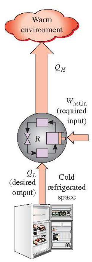
(a) Refrigerator
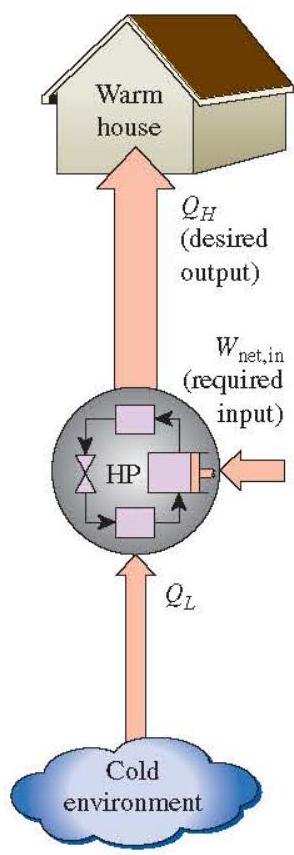
(b) Heat pump
Figure 2-39 The objective of a refrigerator is to remove heat (\left(Q{1}\right)) from the cold medium; the objective of a heat pump is to supply heat (\left(Q{H}\right)) to a warm medium.
The objective of a heat pump, however, is to maintain a heated space at a high temperature. This is accomplished by absorbing heat from a low-temperature source, such as well water or cold outside air in winter, and supplying this heat to a warmer medium such as a house (Fig. 2-39b).
The performance of refrigerators and heat pumps is expressed in terms of the coefficient of performance (COP), defined as
[
\begin{aligned}
& \mathrm{COP}{\mathrm{R}}=\frac{\text { Cooling effect }}{\text { Work input }}=\frac{Q{L}}{W{\text {net,in }}} \
& \mathrm{COP}{\mathrm{HP}}=\frac{\text { Heating effect }}{\text { Work input }}=\frac{Q{H}}{W{\text {net, in }}}
\end{aligned}
]
or in rate form
[
\begin{aligned}
& \mathrm{COP}{\mathrm{R}}=\frac{\dot{\mathrm{Q}}{L}}{\dot{W}{\text {netin }}} \
& \mathrm{COP}{\mathrm{HP}}=\frac{\dot{\mathrm{Q}}{H}}{\dot{W}{\text {net in }}}
\end{aligned}
]
Notice that both (\mathrm{COP}{\mathrm{R}}) and (\mathrm{COP}{\mathrm{HP}}) can be greater than 1. A comparison of Eqs. (2-52) and (2-53) reveals that
[
\mathrm{COP}{\mathrm{HP}}=\mathrm{COP}{\mathrm{R}}+1
]
for fixed values of (Q{L}) and (Q{H}). This relation implies that (\mathrm{COP}{\mathrm{HP}} \geq 1) since (\mathrm{COP}{\mathrm{R}}) is a positive quantity. That is, a heat pump functions, at worst, as a resistance heater, supplying as much energy to the house as it consumes. In reality, however, part of (Q{H}) is lost to the outside air through piping and other devices, and (\mathrm{COP}{\mathrm{HP}}) may drop below unity when the outside air temperature is too low. When this happens, the system normally switches to the fuel (natural gas, propane, oil, etc.) or resistance-heating mode.
The cooling capacity of a refrigeration system-that is, the rate of heat removal from the refrigerated space-is often expressed in terms of tons of refrigeration. The capacity of a refrigeration system that can freeze 1 ton (2000 lbm) of liquid water at (0^{\circ} \mathrm{C}\left(32^{\circ} \mathrm{F}\right)) into ice at (0^{\circ} \mathrm{C}) in 24 h is said to be 1 ton. One ton of refrigeration is equivalent to (211 \mathrm{~kJ} / \mathrm{min}) or (200 \mathrm{Btu} / \mathrm{min}) or (12,000 \mathrm{Btu} / \mathrm{h}). The cooling load of a typical (200-\mathrm{m}^{2}) residence is in the 3 -ton ((10-\mathrm{kW})) range.
EXAMPLE 2-7 A heat pump is used to heat water from 80 to (125^{\circ} \mathrm{F}). The heat absorbed in the evaporator is COP of a Heat Pump (32,000 \mathrm{Btu} / \mathrm{h}) and the power input is 4.3 kW . Determine the rate at which water is heated in gal (/ \mathrm{min}) and the COP of the heat pump.
SOLUTION The rate of heat transfer in the condenser is
[
\dot{Q}{H}=\dot{Q}{L}+\dot{W}_{\mathrm{in}}=32,000 \mathrm{Btu} / \mathrm{h}+(4.3 \mathrm{~kW})\left(\frac{3412 \mathrm{Btu} / \mathrm{h}}{1 \mathrm{~kW}}\right)=46,672 \mathrm{Btu} / \mathrm{h}
]
Taking the specific heat of water to be (1.0 \mathrm{Btu} / \mathrm{bm} \cdot{ }^{\circ} \mathrm{F}), the mass flow rate of water is determined to be
[
\dot{Q}{H}=\dot{m} c{p}\left(T{2}-T{1}\right) \rightarrow \dot{m}=\frac{\dot{Q}{H}}{c{p}\left(T{2}-T{1}\right)}=\frac{46,672 \mathrm{Btu} / \mathrm{h}}{\left(1.0 \mathrm{Btu} / \mathrm{bm} \cdot{ }^{\circ} \mathrm{F}\right)(125-80)^{\circ} \mathrm{F}}=1037 \mathrm{lbm} / \mathrm{h}
]
Taking density of water to be (62.1 \mathrm{lbm} / \mathrm{ft}^{3}), the volume flow rate of water is determined to be
[
\dot{V}=\frac{\dot{m}}{\rho}=\frac{1037 \mathrm{lbm} / \mathrm{h}}{62.1 \mathrm{lbm} / \mathrm{tt}^{3}}\left(\frac{264.17 \mathrm{gal}}{35.315 \mathrm{ft}^{3}}\right)\left(\frac{1 \mathrm{~h}}{60 \mathrm{~min}}\right)=2.08 \mathrm{gal} / \mathrm{min}
]
Finally, the COP of the heat pump is determined from its definition to be
[
\mathrm{COP}{\mathrm{HP}}=\frac{\dot{Q}{\mathrm{H}}}{\dot{W}_{\mathrm{in}}}=\frac{46,672 \mathrm{Btu} / \mathrm{h}}{(4.3 \mathrm{~kW})\left(\frac{3412 \mathrm{Btu} / \mathrm{h}}{1 \mathrm{~kW}}\right)}=\mathbf{3 . 1 8}
]
The most efficient refrigeration and heat pump cycles are referred to as Carnot refrigerators and heat pumps, which consist of totally reversible processes. The coefficients of performance of Carnot refrigerators and heat pumps can be expressed in terms of temperatures as
[
\mathrm{COP}{\mathrm{R}, \text { Carnot }}=\frac{1}{T{H} / T{L}-1}=\frac{T{L}}{T{H}-T{L}}
]
and
[
\mathrm{COP}{\mathrm{HP}, \mathrm{Carnot}}=\frac{1}{1-T{L} / T{H}}=\frac{T{H}}{T{H}-T{L}}
]
where (T{L}) and (T{H}) are the temperatures of the cold and warm mediums, respectively. Notice that both COPs increase as the difference between the two temperatures decreases, that is, as (T{L}) rises or (T{H}) falls. This conclusion is also applicable to actual refrigerators and heat pumps. The reversed Carnot cycle is the most efficient refrigeration cycle operating between two specified temperature levels. The reversed Carnot cycle cannot be approximated in actual devices and is not a realistic model for refrigeration cycles. However, the reversed Carnot cycle can serve as a standard against which actual refrigeration cycles are compared.
REFERENCES
Çengel YA and Cimbala IM. 2018. Fluid Mechanics: Fundamentals and Applications, 4th ed. New York: McGraw-Hill.
Çengel YA and Ghajar AJ. 2015. Heat and Mass Transfer: Fundamentals and Applications, 5th ed. New York: McGraw-Hill.
Çengel, YA, Boles MA, and Kanoğlu M. 2019. Thermodynamics: An Engineering Approach, 9th ed. New York: McGraw-Hill.
Çengel YA, Cimbala IM, and Turner RH. 2016. Fundamentals of Thermal-Fluid Sciences, 5th ed. New York: McGraw-Hill.
Churchill SW. "Friction Factor Equation Spans all Fluid-Flow Regimes," Chemical Engineering, 7 (1977), pp. 91-92. White FM. 2011. Fluid Mechanics, 7th ed. New York: McGraw-Hill.
THERMAL SCIENCES
2-1 What is the scope of the physical sciences called thermal sciences?
2-2 What are the subcategories of thermal-fluid sciences?
2-3 How does the design of a car radiator involve thermodynamics, heat transfer, and fluid mechanics? Explain.
2-4 Which science is not a subcategory of thermal-fluid sciences?
(a) Thermodynamics
(b) Statics
(c) Heat transfer
(d) Fluid mechanics
(e) Thermochemistry
2-5 Which is not a subcategory or application of thermal-fluid sciences?
(a) Refrigeration
(b) Turbomachinery
(c) Power plant design
(d) Mechatronics
(e) Internal combustion engines
THERMODYNAMICS
2-6 Express the first law of thermodynamics. Give an example.
2-7 Express the second law of thermodynamics. Give an example.
2-8 Describe two hypothetical processes, one violating the first law of thermodynamics and the other violating the second law of thermodynamics.
2-9 What does the total energy of a system consist of?
2-10 What is the difference between sensible and latent energies?
2-11 What is the difference between chemical and nuclear energies?
2-12 What is the difference between thermal energy and heat?
2-13 Define enthalpy and flow energy.
2-14 Define the specific heat.
2-15 What is the difference between the constant-volume specific heat and the constant-pressure specific heat? Is one necessarily greater than the other?
2-16 What are the mechanisms of energy transfer to or from a given mass? How do you differentiate them? Give examples.
2-17 What is the difference between the amount and rate of heat transfers? Give three proper units for each term.
2-18 Express general energy balances for a stationary closed system and for a steady-flow system. Simplify these relations when there is a heat input to the system with no work interaction and no changes in kinetic and potential energies. Assume that the fluid involved in both cases is an ideal gas.
2-19 What is the difference between mass flow rate and volume flow rate? What are their units?
2-20 Under what conditions, both the mass and volume flow rates of a fluid through a pipe remains constant?
2-21 How does a pressure cooker cook faster than an ordinary cooker?
2-22 How can water vapor in atmospheric air be condensed? Explain.
2-23 When the pressure is fixed during a phase change process, is the temperature automatically fixed?
2-24 What are the latent heat, latent heat of fusion, and latent heat of vaporization?
2-25 At which temperature, it takes more energy to vaporize a unit mass of water: (100^{\circ} \mathrm{C}) or (150^{\circ} \mathrm{C}) ?
2-26 Which process requires less energy input: melting 1 kg ice at (0^{\circ} \mathrm{C}) or vaporizing 1 kg water at (100^{\circ} \mathrm{C}) ?
2-27 Consider a house with a floor space of (200 \mathrm{~m}^{2}) and an average height of 3 m at sea level, where the standard atmospheric pressure is 101.3 kPa . Initially the house is at a uniform temperature of (13^{\circ} \mathrm{C}). Now the electric heater is turned on, and the heater runs until the air temperature in the house rises to an average value of (21^{\circ} \mathrm{C}). Determine how much heat is absorbed by the air assuming some air escapes through the cracks as the heated air in the house expands at constant pressure. Also, determine the cost of this heat if the unit cost of electricity in that area is (\$ 0.095 / \mathrm{kWh}).
2-28 An 800-W iron is left on the ironing board with its base exposed to the air. About 85 percent of the heat generated in the iron is dissipated through its base whose surface area is (0.15 \mathrm{ft}^{2}), and the remaining 15 percent through other surfaces. Assuming the heat transfer from the surface to be
uniform, determine ( a ) the amount of heat the iron dissipates during a 2-h period, in kWh , (b) the heat flux on the surface of the iron base, in (\mathrm{W} / \mathrm{ft}^{2}), and (c) the total cost of the electrical energy consumed during this (2-\mathrm{h}) period. Take the unit cost of electricity to be (\$ 0.11 / \mathrm{kWh}).
2-29 Infiltration of cold air into a warm house during winter through the cracks around doors, windows, and other openings is a major source of energy loss since the cold air that enters needs to be heated to the room temperature. The infiltration is often expressed in terms of ACH (air changes per hour). An (A C H) of 2 indicates that the entire air in the house is replaced twice every hour by the cold air outside.
Consider an electrically heated house that has a floor space of (180 \mathrm{~m}^{2}) and an average height of 3 m at 1000 m elevation, where the standard atmospheric pressure is 89.6 kPa . The house is maintained at a temperature of (26^{\circ} \mathrm{C}), and the infiltration losses are estimated to amount to 0.5 ACH . Assuming the pressure and the temperature in the house remain constant, determine the amount of energy loss from the house due to infiltration for a day during which the average outdoor temperature is (9^{\circ} \mathrm{C}). Also, determine the cost of this energy loss for that day if the unit cost of electricity in that area is (\$ 0.088 / \mathrm{kWh}).
2-30 Water is heated in an insulated, constant diameter tube by a (7-\mathrm{kW}) electric resistance heater. If the water enters the heater steadily at (10^{\circ} \mathrm{C}) and leaves at (75^{\circ} \mathrm{C}), determine the mass flow rate of water.
2-31 A 2-m (\times 5-\mathrm{m} \times 6-\mathrm{m}) room is to be heated by a baseboard resistance heater. It is desired that the resistance heater be able to raise the air temperature in the room from 7 to (25^{\circ} \mathrm{C}) within 25 min . Assuming no heat losses from the room and an atmospheric pressure of 100 kPa , determine the required power rating of the resistance heater. Assume constant specific heats at room temperature.
2-32 A (5-\mathrm{m} \times 6-\mathrm{m} \times 8-\mathrm{m}) room is to be heated by an electrical resistance heater placed in a short duct in the room. Initially, the room is at (15^{\circ} \mathrm{C}), and the local atmospheric pressure is 98 kPa . The room is losing heat steadily to the outside at a rate of (200 \mathrm{~kJ} / \mathrm{min}). A (300-\mathrm{W}) fan circulates the air steadily through the duct and the electric heater at an average mass flow rate of (50 \mathrm{~kg} / \mathrm{min}). The duct can be assumed to be adiabatic, and there is no air leaking in or out of the room. If it takes 13 min for the room air to reach an average temperature of (25^{\circ} \mathrm{C}), find (a) the power rating of the electric heater and (b) the temperature rise that the air experiences each time it passes through the heater.
2-33 A house has an electric heating system that consists of a (400-\mathrm{W}) fan and an electric resistance heating element placed in a duct. Air flows steadily through the duct at a rate of (0.3 \mathrm{lbm} / \mathrm{s}) and experiences a temperature rise of (8^{\circ} \mathrm{F}). The rate of heat loss from the air in the duct is estimated to be (850 \mathrm{Btu} / \mathrm{h}). Determine the power rating of the electric resistance heating element.
2-34 The ducts of an air heating system pass through an unheated area. As a result of heat losses, the temperature of the air in the duct drops by (2^{\circ} \mathrm{C}). If the mass flow rate of air is (130 \mathrm{~kg} / \mathrm{min}), determine the rate of heat loss from the air to the cold environment.
2-35 Air enters the duct of an air-conditioning system at 15 psia and (50^{\circ} \mathrm{F}) at a volume flow rate of (450 \mathrm{ft}^{3} / \mathrm{min}). The diameter of the duct is 10 in and heat is transferred to the air in the duct from the surroundings at a rate of (2 \mathrm{Btu} / \mathrm{s}). Determine (a) the velocity of the air at the duct inlet and (b) the temperature of the air at the exit.
2-36 Air flows in a 2-in-diameter pipe at 15 psia and (80^{\circ} \mathrm{F}) with a velocity of (12 \mathrm{ft} / \mathrm{s}). Determine the volume and mass flow rates of air.
2-37 Water flows in a (10-\mathrm{cm})-diameter pipe at (15^{\circ} \mathrm{C}) at a rate of (7 \mathrm{~kg} / \mathrm{s}). Determine the velocity and volume flow rate of water?
2-38 A boiler is used to generate saturated water vapor at (200^{\circ} \mathrm{C}). What is the pressure of this water vapor?
2-39 The minimum pressure that can be used in the condenser of a steam power plant is about 10 kPa . If a condenser operates at this pressure, what is the condensation temperature of steam?
2-40 Water is boiled at 1 atm pressure in a coffee maker equipped with an immersion-type electric heating element. The coffee maker initially contains 1 kg of water. Once boiling started, it is observed that half of the water in the coffee maker evaporated in 12 min . If the heat loss from the coffee maker is negligible, what is the power rating of the heating element?
2-41 Saturated steam at (150^{\circ} \mathrm{C}) is obtained from a boiler by transferring heat to water at a rate of 750 kW . Determine the rate at which steam is generated, in (\mathrm{kg} / \mathrm{min}).
2-42 Water at (15^{\circ} \mathrm{C}) is cooled and frozen at 1 atm at a rate of (50 \mathrm{~kg} / \mathrm{h}). Determine the rate at which heat must be removed from the water? The heat of fusion of water at 1 atm is (334 \mathrm{~kJ} / \mathrm{kg}).
2-43 Saturated steam coming off the turbine of a steam power plant at (40^{\circ} \mathrm{C}) condenses on the outside of a (2-\mathrm{cm})-outer-diameter, (60-\mathrm{m})-long tube at a rate of (140 \mathrm{~kg} / \mathrm{h}). Determine the rate of heat transfer from the steam to the cooling water flowing through the pipe.
2-44 The increase in which type of energy manifests itself as a rise in temperature?
(a) Sensible
(b) Latent
(c) Kinetic
(d) Chemical
(e) Potential
2-45 Which energy is the sum of sensible and latent energies?
(a) Nuclear
(b) Potential
(c) Chemical
(d) Internal
(e) Thermal
2-46 Consider the boiling of water in an open pan on an oven. In what form is energy added to water?
(a) Sensible
(b) Latent
(c) Kinetic
(d) Chemical
(e) Potential
2-47 Which energy is needed to push a fluid and to maintain flow?
(a) Sensible
(b) Latent
(c) Flow
(d) Kinetic
(e) Pressure
2-48 The microscopic energy of a flowing fluid is called
(a) Flow work
(b) Latent energy
(c) Chemical energy
(d) Enthalpy
(e) Internal energy
2-49 The specific heat of water is given to be (4.18 \mathrm{~kJ} / \mathrm{kg} \cdot{ }^{\circ} \mathrm{C}). This is equivalent to
(a) (4.18 \mathrm{~kJ} / \mathrm{kg} \cdot \mathrm{K})
(b) (7.52 \mathrm{~kJ} / \mathrm{kg} \cdot{ }^{\circ} \mathrm{F})
(c) (0.0153 \mathrm{~kJ} / \mathrm{kg} \cdot \mathrm{K})
(d) (17.5 \mathrm{Btu} / \mathrm{lbm} \cdot{ }^{\circ} \mathrm{F})
(e) (277.2 \mathrm{~kJ} / \mathrm{kg} \cdot \mathrm{K})
2-50 Choose the incorrect statement.
(a) For liquids, the constant-volume specific heat is approximately equal to constant-pressure specific heat.
(b) For solids, the constant-volume specific heat is approximately equal to constant-pressure specific heat.
(c) The constant-volume specific heat is smaller than constant-pressure specific heat.
(d) For ideal gases, (c{p}=c{v}+R)
(e) The specific heat of a substance depends on temperature only.
2-51 Choose the incorrect statement.
(a) Energy can be transferred to or from a closed system by heat, work, and mass.
(b) Heat is energy transfer due to temperature difference.
(c) Work per unit time is called power.
(d) The amount of heat transferred per unit time is called heat transfer rate.
(e) A rotating shaft is an example for work interaction.
2-52 Which one is not an amount of energy unit?
(a) kWh
(b) kJ
(c) kcal
(d) hp
(e) Btu
2-53 Which one is not a rate of energy unit?
(a) Ton of refrigeration
(b) kW
(c) kcal
(d) hp
(e) Btu/s
2-54 Choose the incorrect statement.
(a) When the density, velocity, and cross-sectional area do not change, the mass flow rate does not change either.
(b) When the velocity and cross-sectional area do not change, the volume flow rate does not change either.
(c) Volume flow rate is equal to mass flow rate divided by density.
(d) When the mass flow rate remains constant during a process of an ideal gas, so does the volume flow rate.
(e) The product of velocity and cross-sectional area is equal to volume flow rate.
2-55 Which process requires the least amount of energy transfer per unit mass of water?
(a) Vaporizing at (100^{\circ} \mathrm{C})
(b) Condensing at (110^{\circ} \mathrm{C})
(c) Vaporizing at (120^{\circ} \mathrm{C})
(d) Condensing at (130^{\circ} \mathrm{C})
(e) Melting at (0^{\circ} \mathrm{C})
2-56 Which process requires the greatest amount of energy transfer per unit mass of water?
(a) Boiling at sea level
(b) Boiling at 2000 m elevation
(c) Boiling at 500 kPa
(d) Condensing at (150^{\circ} \mathrm{C})
(e) Melting at (0^{\circ} \mathrm{C})
HEAT TRANSFER
2-57 What are the modes of heat transfer? What is the driving force for heat transfer? What is the direction of heat transfer?
2-58 What is conduction? What are the mechanisms of conduction in solids, liquids, and gases?
2-59 What do the heat conduction through a medium depend on?
2-60 What is thermal conductivity? What does a low value of thermal conductivity represent?
2-61 What is convection? What is the difference between forced and natural convection?
2-62 What is radiation? How does radiation differ from conduction and convection?
2-63 What are Stefan-Boltzmann law, Stefan-Boltzmann constant, blackbody, blackbody radiation, and emissivity?
2-64 The inner and outer surfaces of a 5-m (\times 6-\mathrm{m}) brick wall of thickness 30 cm and thermal conductivity (0.69 \mathrm{~W} / \mathrm{m} \cdot{ }^{\circ} \mathrm{C}) are maintained at temperatures of 18 and (9^{\circ} \mathrm{C}), respectively. Determine the rate of heat transfer through the wall, in W .
2-65 An aluminum pan whose thermal conductivity is (237 \mathrm{~W} / \mathrm{m} \cdot{ }^{\circ} \mathrm{C}) has a flat bottom whose diameter is 20 cm and thickness 0.6 cm . Heat is transferred steadily to boiling water in the pan through its bottom at a rate of 750 W . If the inner surface of the bottom of the pan is (108^{\circ} \mathrm{C}), determine the temperature of the outer surface of the bottom of the pan.
2-66 Two surfaces of a 1-in-thick plate are maintained at 32 and (212^{\circ} \mathrm{F}), respectively. If it is determined that heat is transferred through the plate at a rate of (180 \mathrm{Btu} / \mathrm{h} \cdot \mathrm{ft}^{2}), determine its thermal conductivity.
2-67 For heat transfer purposes, a standing man can be modeled as a (30-\mathrm{cm}) diameter, (175-\mathrm{cm}-\mathrm{long}) vertical cylinder with both the top and bottom surfaces insulated and with the side surface at an average temperature of (34^{\circ} \mathrm{C}). For a convection heat transfer coefficient of (12 \mathrm{~W} / \mathrm{m}^{2} \cdot{ }^{\circ} \mathrm{C}), determine the rate of heat loss from this man by convection in an environment at (17^{\circ} \mathrm{C}).
2-68 A 2-in-external-diameter, 30-ft-long hot-water pipe at (170^{\circ} \mathrm{F}) is losing heat to the surrounding air at (40^{\circ} \mathrm{F}) by natural convection with a heat transfer coefficient of (5 \mathrm{Btu} / \mathrm{h} \cdot \mathrm{ft}^{2} .{ }^{\circ} \mathrm{F}). Determine the rate of heat loss from the pipe by natural convection.
2-69 A 12-cm-diameter spherical ball whose surface is maintained at a temperature of (110^{\circ} \mathrm{C}) is suspended in the middle of a room at (20^{\circ} \mathrm{C}). If the convection heat transfer coefficient is (15 \mathrm{~W} / \mathrm{m}^{2} \cdot{ }^{\circ} \mathrm{C}) and the emissivity of the surface is 0.6 , determine the total rate of heat transfer from the ball.
2-70 A (1000-\mathrm{W}) iron is left on the ironing board with its base exposed to the air at (23^{\circ} \mathrm{C}). The convection heat transfer coefficient between the base surface and the surrounding air is (35 \mathrm{~W} / \mathrm{m}^{2} \cdot{ }^{\circ} \mathrm{C}). If the base has an emissivity of 0.9 and a surface area of (0.02 \mathrm{~m}^{2}), determine the temperature of the base of the iron.
2-71 A thin metal plate is insulated on the back and exposed to solar radiation on the front surface. The exposed surface of the plate has an absorptivity of 0.8 for solar radiation. If solar radiation is incident on the plate at a rate of (350 \mathrm{~W} / \mathrm{m}^{2}) and the surrounding air temperature is (25^{\circ} \mathrm{C}), determine the surface temperature of the plate when the heat loss by convection equals the solar energy absorbed by the plate. Assume the convection heat transfer coefficient to be (40 \mathrm{~W} / \mathrm{m}^{2} \cdot{ }^{\circ} \mathrm{C}), and disregard heat loss by radiation.
2-72 Which is not a mechanism of heat transfer?
(a) Convection
(b) Radiation
(c) Diffusion
(d) Conduction
(e) None of these
2-73 Which is not a mechanism of conduction in solids, liquids, and gases?
(a) Collisions of molecules
(b) Buoyancy motion
(c) Vibrations of molecules
(d) Transport of free electrons
(e) Diffusion of molecules
2-74 The rate of heat conduction through a medium does not depend on
(a) Surface roughness
(b) Geometry of the medium
(c) Material of the medium
(d) Temperature difference
(e) None of these
2-75 The rate of heat conduction through a plane layer is inversely proportional to
(a) Heat transfer area
(b) Thermal conductivity of the wall
(c) Wall thickness
(d) Temperature difference
(e) None of these
2-76 Which one doubles the rate of heat conduction through a plane layer?
(a) Decreasing area by half
(b) Decreasing thermal conductivity by half
(c) Decreasing temperature difference by half
(d) Decreasing the wall thickness by half
(e) None of these
2-77 The thermal conductivities of copper and rigid foam insulations are, respectively (in (\mathrm{W} / \mathrm{m} \cdot \mathrm{K}) )
(a) 1000,1
(b) (400,0.025)
(c) 50,10
(d) (10,0.5)
(e) (6,0.005)
2-78 The thermal conductivity of water is given to be (0.607 \mathrm{~W} / \mathrm{m} \cdot \mathrm{K}). This is equivalent to
(a) (0.607 \mathrm{~W} / \mathrm{m} \cdot{ }^{\circ} \mathrm{C})
(b) (273.6 \mathrm{~W} / \mathrm{m} \cdot{ }^{\circ} \mathrm{C})
(c) (1.09 \mathrm{~W} / \mathrm{m} \cdot{ }^{\circ} \mathrm{F})
(d) (0.632 \mathrm{Btu} / \mathrm{h} \cdot \mathrm{ft} \cdot{ }^{\circ} \mathrm{F})
(e) (1.99 \mathrm{~W} / \mathrm{ft} \cdot \mathrm{R})
2-79 The thermal conductivities of iron and chromium are 83 and (95 \mathrm{~W} / \mathrm{m} \cdot \mathrm{K}), respectively. What is the thermal conductivity of steel containing 1 percent of chrome?
(a) (97 \mathrm{~W} / \mathrm{m} \cdot \mathrm{K})
(b) (95 \mathrm{~W} / \mathrm{m} \cdot \mathrm{K})
(c) (88 \mathrm{~W} / \mathrm{m} \cdot \mathrm{K})
(d) (83 \mathrm{~W} / \mathrm{m} \cdot \mathrm{K})
(e) (62 \mathrm{~W} / \mathrm{m} \cdot \mathrm{K})
2-80 The convection heat transfer coefficient does not depend on
(a) Surface geometry
(b) Surface conductivity
(c) Fluid velocity
(d) Fluid type
(e) Fluid viscosity
2-81 For which case the convection heat transfer coefficient takes the highest values?
(a) Forced convection of liquids
(b) Forced convection of gases
(c) Boiling and condensation
(d) Free convection of liquids
(e) Free convection of gases
2-82 The emissivity of white paint is
(a) 1
(b) 0.9
(c) 0.5
(d) 0.25
(e) 0
2-83 The emissivity and absorptivity of a blackbody are, respectively
(a) 0,1
(b) (0.5,1)
(c) 0,0
(d) 1,0
(e) 1,1
2-84 When a surface is completely enclosed by a much larger surface separated by air, the net rate of radiation heat transfer between these two surfaces does not depend on
(a) Surface area of small surface
(b) Surface temperature
(c) Temperature of surrounding surface
(d) Air temperature
(e) Stefan-Boltzmann constant
2-85 Which one is not a correct unit for combined heat transfer coefficient?
(a) (\mathrm{Btu} / \mathrm{ft}^{2} \cdot{ }^{\circ} \mathrm{F})
(b) (\mathrm{W} / \mathrm{m}^{2} \cdot \mathrm{~K})
(c) (\mathrm{W} / \mathrm{m}^{2} \cdot{ }^{\circ} \mathrm{C})
(d) (\mathrm{kJ} / \mathrm{s} \cdot \mathrm{ft}^{2} \cdot \mathrm{~K})
(e) (\mathrm{kcal} / \mathrm{h} \cdot \mathrm{ft}^{2} \cdot \circ \mathrm{~F})
FLUID MECHANICS
2-86 Define fluid and fluid mechanics.
2-87 What is the difference between a liquid and a gas? Explain.
2-88 What is viscosity? What is it due to?
2-89 What is the difference between dynamics viscosity and kinematic viscosity? What are their units?
2-90 When the pressure drop in pipe is available, in kPa , how do you determine the pumping power requirement, in kW , to overcome this pressure drop?
2-91 The dynamic viscosity of air at 101 kPa and (10^{\circ} \mathrm{C}) is (1.778 \times 10^{-5} \mathrm{~kg} / \mathrm{m} \cdot \mathrm{s}). What is the kinematic viscosity of air, in (\mathrm{m}^{2} / \mathrm{s}) and stoke?
2-92 The kinematic viscosity of air at 1 atm and (100^{\circ} \mathrm{F}) is (1.809 \times 10^{-4} \mathrm{ft}^{2} / \mathrm{s}). What is the dynamic viscosity of air, in lbm/ft (\cdot)s?
2-93 The viscosity of a fluid is to be measured by a viscometer constructed of two (85-\mathrm{cm})-long concentric cylinders. The outer diameter of the inner cylinder is 15 cm , and the gap between the two cylinders is 1 mm . The inner cylinder is rotated at 450 rpm , and the torque is measured to be 0.9 Nm . Determine the viscosity of the fluid.
2-94 The viscosity of a fluid is to be measured by a viscometer constructed of two 2-ft-long concentric cylinders. The inner diameter of the outer cylinder is 6 in, and the gap between the two cylinders is 0.05 in . The outer cylinder is rotated at 300 rpm , and the torque is measured to be (1.2 \mathrm{lbf} \cdot \mathrm{ft}). Determine the viscosity of the fluid.
2-95 Water at (15^{\circ} \mathrm{C}\left(\rho=999.7 \mathrm{~kg} / \mathrm{m}^{3}\right.) and (\left.\mu=1.307 \times 10^{-3} \mathrm{~kg} / \mathrm{m} \cdot \mathrm{s}\right)) is flowing steadily in a (0.25-\mathrm{cm}-) diameter, (35-\mathrm{m})-long pipe at an average velocity of (1.2 \mathrm{~m} / \mathrm{s}). Determine ( (a) ) the pressure drop, (b) the head loss, and (c) the pumping power requirement to overcome this pressure drop.
2-96 Air enters a 12-m-long section of a rectangular duct of cross section (15 \mathrm{~cm} \times 20 \mathrm{~cm}) made of commercial steel at 1 atm and (23^{\circ} \mathrm{C}) at an average velocity of (5 \mathrm{~m} / \mathrm{s}). Disregarding the entrance effects, determine the fan power needed to overcome the pressure losses in this section of the duct. The properties of air at 1 atm and (35^{\circ} \mathrm{C}) are (\rho=1.145 \mathrm{~kg} / \mathrm{m}^{3}, \mu=1.895 \times 10^{-5} \mathrm{~kg} / \mathrm{m} \cdot \mathrm{s}), and (v=1.655 \times 10^{-5} \mathrm{~m}^{2} / \mathrm{s}).
2-97 Water at (72^{\circ} \mathrm{F}) passes through 0.75 -in-internaldiameter copper tubes at a rate of (1.3 \mathrm{lbm} / \mathrm{s}). Determine the pumping power per foot of pipe length required to maintain this flow at the specified rate. The density and dynamic viscosity of water at (60^{\circ} \mathrm{F}) are (\rho=62.36 \mathrm{lbm} / \mathrm{ft}^{3}) and (\mu=2.713 \mathrm{lbm} / \mathrm{ft} \cdot \mathrm{h}=) (7.536 \times 10^{-4} \mathrm{lbm} / \mathrm{ft} \cdot \mathrm{s}).
2-98 Which science deals with liquid flows in pipes and open channels?
(a) Hydrology
(b) Hydraulics
(c) Fluid dynamics
(d) Aerodynamics
(e) Gas dynamícs
2-99 Which one is not a correct unit for dynamic or kinematic viscosity?
(a) (\mathrm{N} \cdot \mathrm{s} / \mathrm{m}^{2})
(b) (\mathrm{ft}^{2} / \mathrm{min})
(c) (\mathrm{kg} / \mathrm{m} \cdot \mathrm{s})
(d) (\mathrm{m}^{2} / \mathrm{s})
(e) (\mathrm{Pa} \cdot \mathrm{s} / \mathrm{m}^{2})
2-100 When the temperature increases
(a) Viscosity of a gas increases and viscosity of a liquid decreases.
(b) Viscosity of a gas and a liquid increases.
(c) Viscosity of a gas decreases and viscosity of a liquid increases.
(d) Viscosity of a gas and a liquid decreases.
(e) Viscosity of a gas and a liquid remain constant.
2-101 The pressure drop during laminar flow of a fluid in a pipe does not depend on
(a) Friction coefficient
(b) Pipe diameter
(c) Surface roughness
(d) Fluid density
(e) Fluid velocity
2-102 When the diameter of a pipe doubles, the pumping power requirement in a laminar-flow piping system decreases by a factor of
(a) 2
(b) 4
(c) 8
(d) 16
(e) 32
THERMOCHEMISTRY
2-103 What are the combustible elements in common fossil fuels?
2-104 What are LPG and LNG? Explain.
2-105 What is a fuel? What is combustion?
2-106 The total mass of reactants must be equal to that of products in a chemical reaction. Is this also true for mole numbers?
2-107 What is stoichiometric air?
2-108 Define enthalpy of reaction, enthalpy of combustion, and enthalpy of formation.
2-109 The enthalpy of formation of (\mathrm{CO}{2}) at the standard reference state is (-393,520 \mathrm{~kJ} / \mathrm{kmol}). What does the negative sign represent?
2-110 What is the heating value of a fuel?
2-111 What is the difference between the higher heating value (HHV) and lower heating value (LHV)? How are they related to each other?
2-112 Propane fuel (\left(\mathrm{C}{3} \mathrm{H}{8}\right)) is burned in the presence of air. Assuming that the combustion is theoretical, determine (a) the mass fraction of carbon dioxide and (b) the mole and mass fractions of the water vapor in the products. (c) Determine how much carbon dioxide is produced when 5 kg of propane is burned?
2-113 Ethyl alcohol (\left(\mathrm{C}{2} \mathrm{H}{5} \mathrm{OH}\right)) is burned with 50 percent excess air. (a) Calculate the mole fractions of the products formed and the reactants. (b) Calculate the mass of carbon dioxide, water and oxygen contained in the products per unit mass of fuel burned. (c) Calculate the airfuel ratio.
2-114 Propylene (\left(\mathrm{C}{3} \mathrm{H}{6}\right)) is burned with 100 percent excess air during a combustion process. Assuming complete combustion and a total pressure of 105 kPa , determine (a) the air-fuel ratio and (b) the temperature at which the water vapor in the products will start condensing.
2-115 Methane (\left(\mathrm{CH}{4}\right)) is burned with dry air. The volumetric analysis of the products on a dry basis is 5.20 percent (\mathrm{CO}{2}, 0.33) percent (\mathrm{CO}, 11.24) percent (\mathrm{O}{2}), and 83.23 percent (\mathrm{N}{2}). Determine (a) the airfuel ratio and (b) the percentage of theoretical air used.
2-116 The higher heating value of propane (\left(\mathrm{C}{3} \mathrm{H}{8}\right)) is (50,330 \mathrm{~kJ} / \mathrm{kg}). Calculate its lower heating value.
2-117 The lower heating value of isopentane (\left(\mathrm{C}{5} \mathrm{H}{12}\right)) is (19,310 \mathrm{Btu} / \mathrm{lbm}). Calculate its higher heating value.
2-118 The enthalpy of combustion of butane (\left(\mathrm{C}{4} \mathrm{H}{10}\right)) at (25^{\circ} \mathrm{C}) and 1 atm is calculated to be 2857 MJ/kmol when the water in the products is in the liquid form. Calculate the lower and higher heating values of butane.
2-119 Determine the enthalpy of combustion of methane (\left(\mathrm{CH}{4}\right)) at (25^{\circ} \mathrm{C}) and 1 atm , using the enthalpy of formation data from Table A-6. Assume that the water in the products is in the liquid form.
2-120 Calculate the HHV and LHV of gaseous n-octane fuel (\left(\mathrm{C}{8} \mathrm{H}{18}\right)). Compare your results with the values in Table A-7.
2-121 Calculate the higher and lower heating values of a coal from Illinois, which has an ultimate analysis (by mass) as 67.40 percent (\mathrm{C}, 5.31) percent (\mathrm{H}{2}, 15.11) percent (\mathrm{O}{2}, 1.44) percent (\mathrm{N}{2}, 2.36) percent S , and 8.38 percent ash (non combustibles). The enthalpy of formation of (\mathrm{SO}{2}) is (-297,100 \mathrm{~kJ} / \mathrm{kmol}).
2-122 Octane gas (\left(\mathrm{C}{8} \mathrm{H}{18}\right)) is burned with 100 percent excess air in a constant pressure burner. The air and fuel enter this burner steadily at standard conditions and the products of combustion leave at (257^{\circ} \mathrm{C}). Calculate the rate of heat transfer from this burner when fuel is burned at a rate of (2.5 \mathrm{~kg} / \mathrm{min}). Enthalpy values are given in below table.
\begin{tabular}{llll}
\hline & \begin{tabular}{l}
(\bar{h}{f}^{\circ}) \
(\mathrm{kJ} / \mathrm{kmol})
\end{tabular} & \begin{tabular}{l}
(\bar{h}{298 \mathrm{~K}}) \
(\mathrm{~kJ} / \mathrm{kmol})
\end{tabular} & \begin{tabular}{l}
(\bar{h}{530 \mathrm{~K}}) \
(\mathrm{~kJ} / \mathrm{kmol})
\end{tabular} \
\hline (\mathrm{C}{8} \mathrm{H}{18}(\mathrm{~g})) & (-208,450) & - & - \
(\mathrm{O}{2}) & 0 & 8682 & 15,708 \
(\mathrm{~N}{2}) & 0 & 8669 & 15,469 \
(\mathrm{H}{2} \mathrm{O}(g)) & (-241,820) & 9904 & 17,889 \
(\mathrm{CO}{2}) & (-393,520) & 9364 & 19,029 \
\hline
\end{tabular}
2-123 Diesel fuel (\left(\mathrm{C}{12} \mathrm{H}{26}\right)) at (77^{\circ} \mathrm{F}) is burned in a steady-flow combustion chamber with 20 percent excess air that also enters at (77^{\circ} \mathrm{F}). The products leave the combustion chamber at 800 R . Assuming combustion is complete, determine the required mass flow rate of the diesel fuel to supply heat at a rate of (1250 \mathrm{Btu} / \mathrm{s}). Enthalpy values are given in below table.
\begin{tabular}{llll}
\hline & (\bar{h}{f}^{\circ}) & (\bar{h}{537 \mathrm{R}}) & (\bar{h}{800 \mathrm{R}}) \
Substance & Btu/lbmol & Btu/lbmol & Btu/lbmol \
\hline (\mathrm{C}{12} \mathrm{H}{26}) & (-125,190) & - & - \
(\mathrm{O}{2}) & 0 & 3725.1 & 5602.0 \
(\mathrm{~N}{2}) & 0 & 3729.5 & 5564.4 \
(\mathrm{H}{2} \mathrm{O}(g)) & (-104,040) & 4258.0 & 6396.9 \
(\mathrm{CO}{2}) & (-169,300) & 4027.5 & 6552.9 \
\hline
\end{tabular}
2-124 A coal from Texas which has an ultimate analysis (by mass) as 39.25 percent (C, 6.93) percent (\mathrm{H}{2}, 41.11) percent (\mathrm{O}{2}, 0.72) percent (\mathrm{N}{2}, 0.79) percent S , and 11.20 percent ash (noncombustibles) is burned steadily with 40 percent excess air in a power plant boiler. The coal and air enter this boiler at standard conditions and the products of combustion in the smokestack are at (127^{\circ} \mathrm{C}). Calculate the heat transfer, in (\mathrm{kJ} / \mathrm{kg}) fuel, in this boiler. Include the effect of the sulfur in the energy analys is by noting that sulfur dioxide has an enthalpy of formation of (-297,100 \mathrm{~kJ} / \mathrm{kmol}) and an average specific heat at constant pressure of (\bar{c}{p}=41.7 \mathrm{~kJ} / \mathrm{kmol} \cdot \mathrm{K}). Enthalpy values are given in below table.
\begin{tabular}{llll}
\hline & \begin{tabular}{l}
(\bar{h}{f}^{\circ}) \
(\mathrm{kJ} / \mathrm{kmol})
\end{tabular} & \begin{tabular}{l}
(\bar{h}{298 \mathrm{~K}}) \
(\mathrm{~kJ} / \mathrm{kmol})
\end{tabular} & \begin{tabular}{l}
(\bar{h}{400 \mathrm{~K}}) \
(\mathrm{~kJ} / \mathrm{kmol})
\end{tabular} \
\hline (\mathrm{O}{2}) & 0 & 8682 & 11,711 \
(\mathrm{~N}{2}) & 0 & 8669 & 11,640 \
(\mathrm{H}{2} \mathrm{O}(\mathrm{g})) & (-241,820) & 9904 & 13,356 \
(\mathrm{CO}{2}) & (-393,520) & 9364 & 13,372 \
(\mathrm{SO}{2}) & (-297,100) & - & - \
\hline
\end{tabular}
2-125 Which is not a fuel?
(a) Hydrogen
(b) Water
(c) Carbon
(d) Sulfur
(e) Carbon monoxide
2-126 When a hydrocarbon fuel is burned completely, the mass of carbon dioxide formed is always (\qquad) the mass of fuel.
(a) Less than
(b) Equal to
(c) Greater than
2-127 When a hydrocarbon fuel is burned completely, the mass of water formed is always (\qquad) the mass of fuel.
(a) Less than
(b) Equal to
(c) Greater than
2-128 When a fuel is burned with 200 percent theoretical air, this is equivalent to
(a) (100 \%) stoichiometric air
(b) (200 \%) excess air
(c) (300 \%) stoichiometric air
(d) (100 \%) excess air
(e) (100 \%) deficiency of air
2-129 When a fuel is burned with 75 percent theoretical air, this is equivalent to
(a) (175 \%) stoichiometric air
(b) (75 \%) excess air
(c) (25 \%) stoichiometric air
(d) (75 \%) deficiency of air
(e) (25 \%) deficiency of air
2-130 When a fuel is burned completely, the products cannot contain
(a) (\mathrm{H}{2})
(b) (\mathrm{O}{2})
(c) (\mathrm{CO}{2})
(d) (\mathrm{N}{2})
(e) (\mathrm{H}{2} \mathrm{O})
2-131 When a fossil fuel is burned completely, the products can contain
(a) C
(b) (\mathrm{H}{2})
(c) CO
(d) OH
(e) (\mathrm{SO}{2})
2-132 When a fuel is burned completely with stoichiometric air, the products cannot contain
(a) (\mathrm{SO}{2})
(b) (\mathrm{O}{2})
(c) (\mathrm{CO}{2})
(d) (\mathrm{N}{2})
(e) (\mathrm{H}{2} \mathrm{O})
2-133 The enthalpy of a substance at a specified state due to its chemical composition is called
(a) Enthalpy of reaction
(b) Enthalpy of combustion
(c) Enthalpy of formation
(d) Lower heating value
(e) Higher heating value
2-134 The higher heating value of carbon monoxide (CO) is (10,100 \mathrm{~kJ} / \mathrm{kg}) and the enthalpy of vaporization of water to at (25^{\circ} \mathrm{C}) is (h_{f g}=2442 \mathrm{~kJ} / \mathrm{kg}). What is the lower heating value of CO ?
(a) (7658 \mathrm{~kJ} / \mathrm{kg})
(b) (10,100 \mathrm{~kJ} / \mathrm{kg})
(c) (12,542 \mathrm{~kJ} / \mathrm{kg})
(d) (5216 \mathrm{~kJ} / \mathrm{kg})
(e) (8879 \mathrm{~kJ} / \mathrm{kg})
HEAT ENGINES AND POWER PLANTS
2-135 What are the characteristics of all heat engines?
2-136 What is a working fluid?
2-137 A steam power plant receives heat from a furnace at a rate of (290 \mathrm{GJ} / \mathrm{h}). Heat losses to the surrounding air from the steam as it passes through the pipes and other components are estimated to be about (5 \mathrm{GJ} / \mathrm{h}). If the waste heat is transferred to the cooling water at a rate of (160 \mathrm{GJ} / \mathrm{h}), determine (a) net power output and (b) the thermal efficiency of this power plant.
2-138 A car engine with a power output of 140 hp has a thermal efficiency of 30 percent. Determine the rate of fuel consumption if the heating value of the fuel is (19,000 \mathrm{Btu} / \mathrm{lbm}).
2-139 A 900-MW steam power plant, which is cooled by a nearby river, has a thermal efficiency of 40 percent. Determine the rate of heat transfer to the river water. Also, determine the maximum thermal efficiency of this power plant if the temperatures of the furnace and river are (1000 \mathrm{and} 20^{\circ} \mathrm{C}), respectively.
2-140 An automobile engine consumes fuel at a rate of (22 \mathrm{~L} / \mathrm{h}) and delivers 55 kW of power to the wheels. If the fuel has a heating value of (44,000 \mathrm{~kJ} / \mathrm{kg}) and a density of (0.75 \mathrm{~g} / \mathrm{cm}^{3}), determine the efficiency of this engine.
2-141 A coal power plant produces 5 million kWh of electricity per year consuming coal with a heating value of (23,500 \mathrm{~kJ} / \mathrm{kg}). If the plant consumes 2400 tons of coal per year, determine the overall plant efficiency.
2-142 A natural gas-fired power plant produces 400 MW of power with an overall plant efficiency of 43 percent.
(a) Determine the rate of natural gas consumption, in therm (/ \mathrm{h}). Note that 1 therm (=100,000 \mathrm{Btu}=) (105,500 \mathrm{~kJ}).
(b) The amount of electricity produced per year if the plant operates 8200 h a year.
2-143 A natural gas-fired power plant generates 800 MW power consuming natural gas at a rate of (33 \mathrm{~kg} / \mathrm{s}). Determine the overall plant efficiency. The heating value of natural gas is (50,000 \mathrm{~kJ} / \mathrm{kg}).
2-144 Which plant truly operates on a thermodynamic cycle?
(a) Gas turbine
(b) Steam power plant
(c) Gasoline automobile engine
(d) Diesel automobile engine
(e) Solar photovoltaic panel
2-145 Which is not a heat engine?
(a) Gas turbine
(b) Steam power plant
(c) Automobile engine
(d) Hydroelectric power plant
(e) Solar photovoltaic panel
2-146 Which equation is not correct for heat engines?
(a) (W{\text {net,out }}=Q{\text {in }}-Q{\text {out }})
(b) (W{\text {net, out }}=W{\text {out }}-W{\text {in }})
(c) (Q{\text {in }}=W{\text {out }}+W{\text {in }})
(d) (\eta{\text {th }}=1-\frac{Q{\text {out }}}{Q{\text {in }}})
(e) (\eta{\text {th }}=\frac{W{\text {net, out }}}{Q_{\text {in }}})
REFRIGERATORS AND HEAT PUMPS
2-147 What is a refrigerator? What is an air conditioner?
2-148 The second law of thermodynamics requires that heat cannot flow from low temperature regions to high-temperature ones. Does the operation of a refrigerator violate this principle? Explain.
2-149 What is a heat pump? What is the difference between a refrigerator and a heat pump? What is the difference between a heat pump and an air conditioner?
2-150 Define the coefficient of performance (COP) of a refrigerator and a heat pump in words. Can they be greater than 1 ?
2-151 Someone claims that the COP of a refrigerator cannot be greater than 1 . She says this would be a violation of the first law of thermodynamics since a refrigerator cannot provide more cooling than the work it consumes. Can she be right? Explain.
2-152 How can the COP of a Carnot refrigerator and a heat pump be increased?
2-153 Why are we interested in the Carnot refrigerator and Carnot heat pump even though they cannot be approximated in practice?
2-154 Consider two identical freezers operating in the same environment. The temperature of freezer A is set to (-18^{\circ} \mathrm{C}) while the temperature of freezer B is set to (-24^{\circ} \mathrm{C}). Which freezer consumes more electricity for the same rate of heat removal? Why?
2-155 Consider two identical refrigerators, both maintaining the refrigerated compartment at the same temperature. Refrigerator A operates in a kitchen at (20^{\circ} \mathrm{C}) while refrigerator B operates in a kitchen at (25^{\circ} \mathrm{C}). Which refrigerator consumes more electricity for the same rate of heat removal? Why?
2-156 A food section is maintained at (-8^{\circ} \mathrm{C}) by a refrigerator in an environment at (27^{\circ} \mathrm{C}). The rate of heat gain to the food section is estimated to be (850 \mathrm{~kJ} / \mathrm{h}) and the heat rejection in the condenser is (1250 \mathrm{~kJ} / \mathrm{h}). Determine (a) the power input to the compressor in kW and (b) the COP of the refrigerator.
2-157 A (12,000 \mathrm{Btu} / \mathrm{h}) split air conditioner is used to maintain a small room at (25^{\circ} \mathrm{C}) when the ambient temperature is (35^{\circ} \mathrm{C}). The air conditioner is running at full load under these conditions. The power input to the compressor is 1.7 kW . Determine (a) the rate of heat rejected in the condenser in (\mathrm{Btu} / \mathrm{h}), (b) the COP of the air conditioner, and (c) the rate of cooling in Btu/h if the air conditioner operated as a Carnot refrigerator for the same power input.
2-158 Heat is absorbed from a space at (44^{\circ} \mathrm{F}) at a rate of (22 \mathrm{Btu} / \mathrm{s}) by a cooling system. Heat is rejected to water in the condenser. Water enters the condenser at (60^{\circ} \mathrm{F}) at a rate of (1.85 \mathrm{lbm} / \mathrm{s}). The COP of the system is estimated to be 1.85 . Determine ( (a) ) the power input to the system, in kW and (b) the temperature of the water at the exit of the condenser. The specific heat of water is (1.0 \mathrm{Btu} / \mathrm{lbm} \cdot{ }^{\circ} \mathrm{F}).
2-159 A room is maintained at (23^{\circ} \mathrm{C}) by a heat pump by rejecting heat to an environment at (6^{\circ} \mathrm{C}). The rate of heat loss from the room to the environment is estimated to be (36,000 \mathrm{~kJ} / \mathrm{h}) and the power input to the compressor is 3.3 kW . Determine (a) the rate of heat absorbed from the environment in (\mathrm{kJ} / \mathrm{h}), (b) the COP of the heat pump, and (c) the maximum rate of heat supply to the room for the given power input.
2-160 Which one is not a heating or cooling system?
(a) Compressor
(b) Heat pump
(c) Boiler
(d) Air conditioner
(e) Evaporative cooler
2-161 Which one cannot be smaller than 1?
(a) Efficiency of a boiler
(b) Thermal efficiency of a heat engine
(c) COP of an air conditioner
(d) COP of a refrigerator
(e) COP of a heat pump
2-162 The coefficient of performance of an electric resistance heater is
(a) 0
(b) 0.5
(c) 1.0
(d) 2.0
(e) 3.0
2-163 A heat pump supplies 5 kW of heat to a room while consuming 2.5 kW of electricity. If this heat pump is replaced by an electric resistance heater supplying the same rate of heat to the room, the rate of electricity consumption will be
(a) 0 kW
(b) 2.5 kW
(c) 5.0 kW
(d) 7.5 kW
(e) 10 kW
2-164 A household refrigerator consumes 1 kW of electricity and has a COP of 1.5. The net effect of this refrigerator on the kitchen air is
(a) 1 kW cooling
(b) 1 kW heating
(c) 1.5 kW cooling
(d) 1.5 kW heating
(e) 2.5 kW heating
2-165 A window air conditioner is placed in the middle of a room. The air conditioner consumes 2 kW of electricity and has a COP of 2 . The net effect of this air conditioner on the room is
(a) 2 kW cooling
(b) 2 kW heating
(c) 4 kW cooling
(d) 4 kW heating
(e) 6 kW heating